
Single module modifiers
With the modifiers scope set to Single module, you apply exact adjustments to chosen cells of one module. This is the workflow to use when you want to study a specific, deterministic pattern such as a named shaded cell, a degraded row, or a deliberate current mismatch.
Adding a modifier
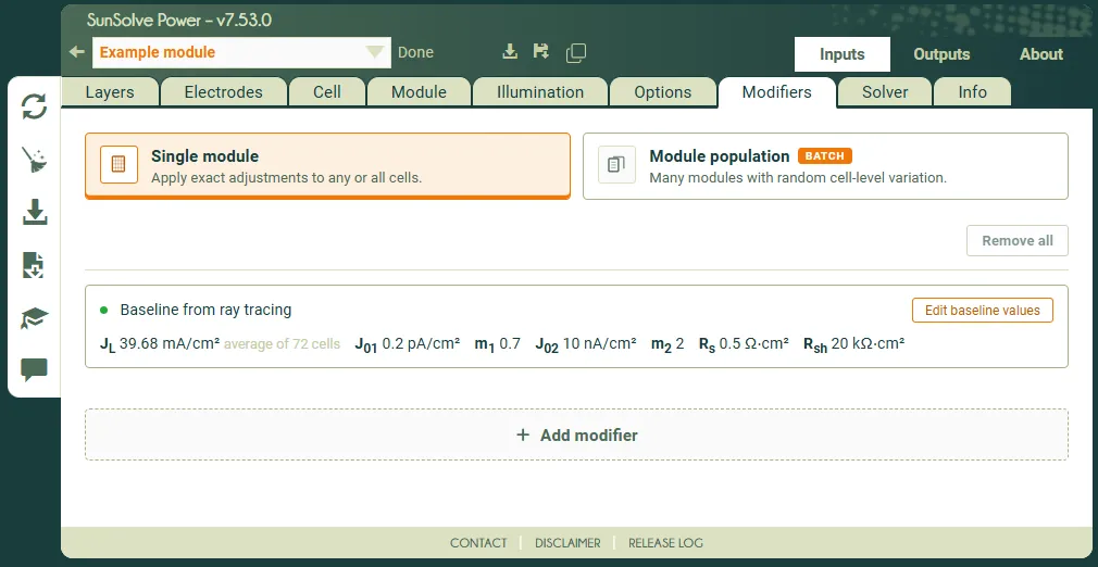
Section link: Adding a modifierWith Single module selected, click Add modifier to create a modifier card. There is no limit to how many modifiers you can add. Each card is listed in the order it was added, and the cards are applied in that order during calculation.
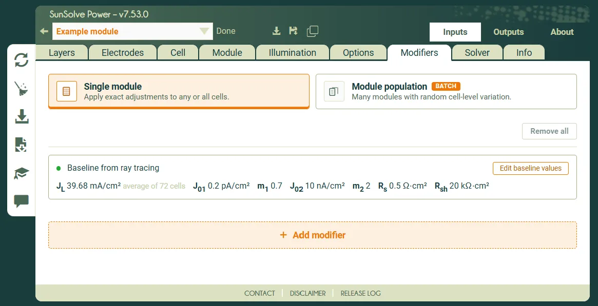
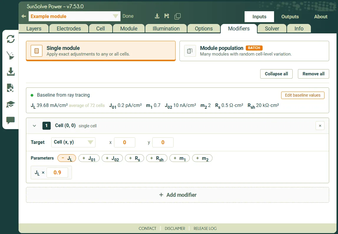
Each card has two parts: a Parameters section that chooses which equivalent-circuit parameters to scale, and a Target section that chooses which cells and circuit the card applies to.
The example below applies one modifier to cell (0, 0), in the bottom-left corner of the module. It reduces to 90% of the value calculated by ray tracing and the solve.
Selecting parameters
Section link: Selecting parametersThe Parameters row shows a pill for every equivalent-circuit parameter that is enabled in the target circuit (as configured on the Inputs → Cell tab). Click a pill to add that parameter to the card; a matching multiplier field appears below it. Click the pill again, or the × next to the field, to remove the parameter. You may add as many parameters to a single card as needed.
Each parameter field holds a multiplier applied to that cell’s baseline value.
Targeting cells and circuit
Section link: Targeting cells and circuitThe Target selector chooses which cells the card applies to:
- Every cell: applies the multipliers to all cells (the default).
- Cell (x, y): applies to the single cell at column
x, rowy. - Row: applies to every cell in row
y. - Column: applies to every cell in column
x.
Cell coordinates are zero-based. Both x and y run from 0 to one less than the number of cells along the corresponding axis. The cell map on the output tabs uses the same coordinates, so you can read a cell’s position there before entering it here.
For a module with more than one circuit (for example a tandem cell), a circuit selector appears on the card so you can choose which sub-circuit the modifier targets. The multipliers are applied only to that circuit.
Applying multiple modifiers to the same cell
Section link: Applying multiple modifiers to the same cellIf two or more cards target the same cell, all of them are applied, in the order the cards appear in the list. Because modifiers are multiplicative, the combined effect on a parameter is the product of every multiplier that targets that cell.
For example, if one card reduces the JL of every cell in row 5 to 90% and a second card raises the JL of every cell in column 2 to 110%, then the cell where the row and column overlap is scaled by both: 0.9 × 1.1 = 0.99, leaving it almost unchanged. Every other affected cell receives only one of the two multipliers.
Practical example: individual cell shading
Section link: Practical example: individual cell shadingSimulate shading on specific cells of a 144 half-cut cell module:
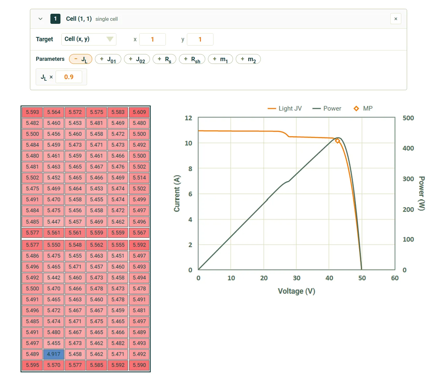
- Create the module and solve the optical model. The cell map and IV curve are shown below.

- Add a modifier:
- Add the JL parameter and set its multiplier to
0.9(a 10% light reduction). - Set the target to Cell (x, y) with x = 1, y = 1.
- The electrical output updates to reflect the reduced cell current and its impact on the IV curve.
- Add the JL parameter and set its multiplier to
- Add a second modifier:
- Add the JL parameter and set its multiplier to
0.8(a 20% light reduction). - Set the target to Cell (x, y) with x = 5, y = 11.
- Two cells are now shaded.
- Add the JL parameter and set its multiplier to
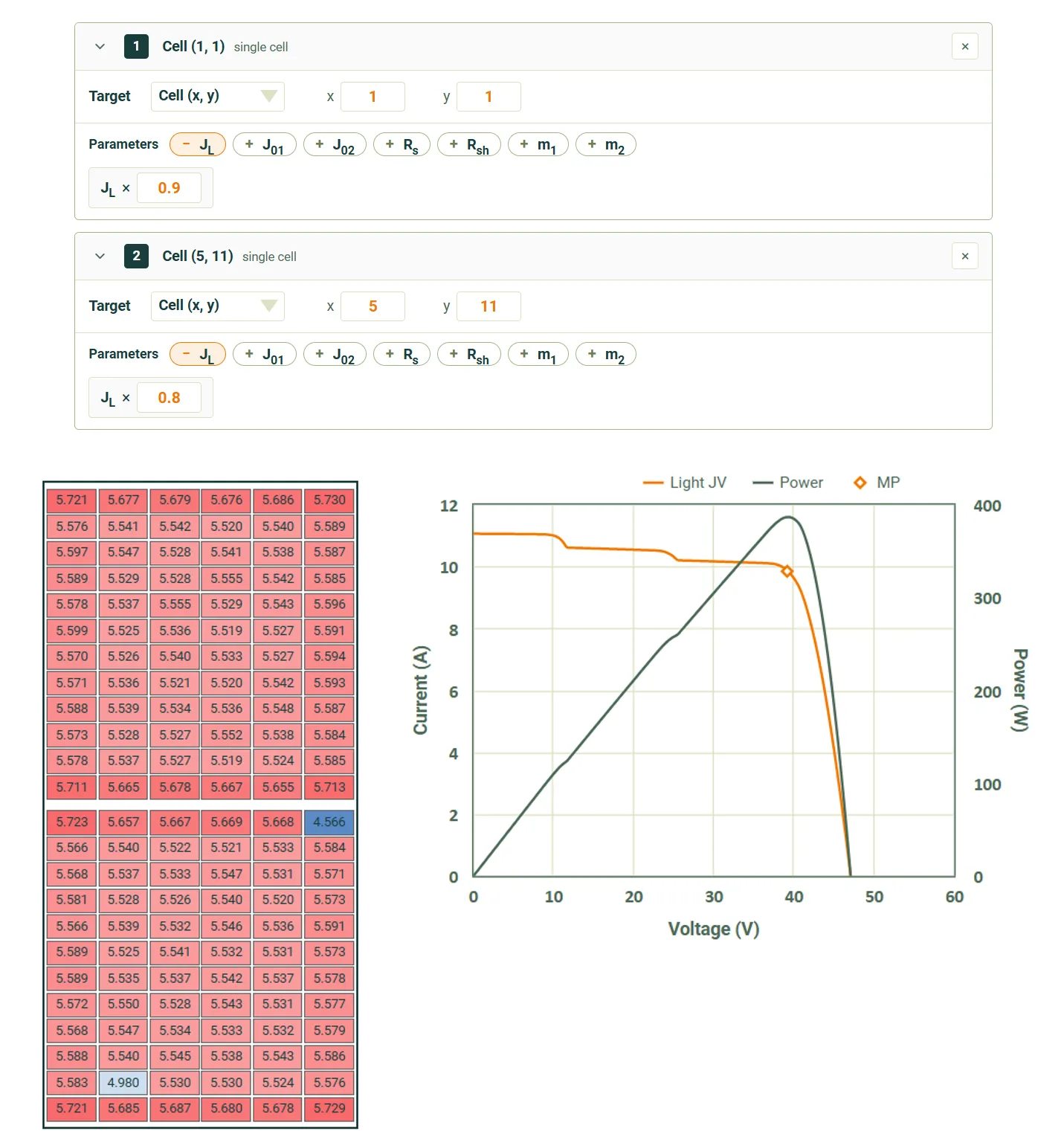
With these modifiers applied, the two targeted cells have their JL reduced to 90% and 80% of the optical values respectively, while all other cells remain unaffected. The current-limiting effect in the strings containing these cells creates characteristic steps in the IV curve and reduces maximum power output due to increased mismatch losses.