Cell geometry
The cell geometry inputs define the shape and size of each solar cell. These are configured in the Geometry section of the Inputs → Cell tab.
The cell shape and dimensions directly affect both the optical ray tracing (determining the active area where light is absorbed) and the electrical simulation (cell area is used to scale current densities and resistances to circuit values — see current density vs. current notation).
Cell shape
Section link: Cell shapeThe shape of each cell is selected from the Shape dropdown. Four options are available:
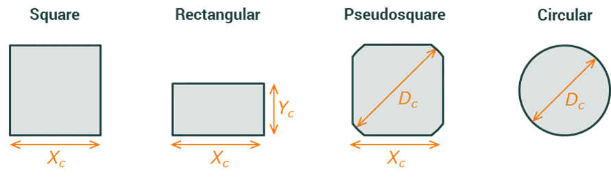
Cell dimensions
Section link: Cell dimensionsThe dimension inputs shown depend on the selected shape:
For a square cell, both the X and Y dimensions of the cell are equal to . For a pseudosquare cell, the corners are rounded arcs with diameter ; the cell is square with side length but with the four corners cut to follow a circle of diameter . The diameter must be greater than or equal to the side length ().
Cell area
Section link: Cell areaThe cell area is computed automatically from the shape and dimensions and is displayed as a read-only output in cm². This value is used throughout the simulation — for example, to convert between current density (, in A/cm²) and current (, in A), and between specific resistance (Ω·cm²) and circuit resistance (Ω).
The formula depends on the selected shape:
-
Square:
-
Rectangular:
-
Circular:
-
Pseudosquare: If the diameter is large enough that the corners have no effect (), the area is simply . Otherwise, the rounded corners reduce the area:
where is the width of the flat side between corners and is the angular extent of the curved sections.