Equivalent circuit model
SunSolve Power models the electrical behaviour of photovoltaic cells using an equivalent circuit approach. Each solar cell is represented by a circuit that includes a current source for the light-generated current, along with diodes and resistors that represent the different loss mechanisms within a solar cell.
This circuit is widely used in photovoltaic simulation to calculate the electrical output of cells and modules under a wide range of operating conditions.
SunSolve Power applies this model at the cell level, allowing detailed analysis of cell-to-cell variations and electrical topology effects within the module.
Purpose of the equivalent circuit
Section titled “Purpose of the equivalent circuit”The equivalent circuit relates the current produced by a cell I to the voltage applied to the cell V. It can therefore be used to predict a cell’s IV curve—and hence its efficiency—under different operating conditions.
SunSolve supports multiple equivalent circuit configurations:
- One-diode model: The simplest form, containing just the primary diode component along with series and shunt resistances
- Two-diode model: Adds a second diode to improve accuracy for cells with distinct recombination characteristics
- Three-diode model: Includes an additional resistive-limited enhanced recombination component for complex IV curve behaviour
The primary component of any equivalent circuit is the diode that represents the junction of the solar cell, defined by its saturation current I01 and ideality factor m1. Additional components can be activated as needed to accurately represent the electrical characteristics of specific cell technologies.
Current density vs. current notation
Section titled “Current density vs. current notation”The equivalent circuit parameters in SunSolve are entered and stored as current densities (denoted J, with units of A/cm²) normalised by the cell area. This approach allows for direct comparison between cells of different sizes and simplifies parameter extraction from measured data.
In the equations presented on this page, currents are written using I notation (amperes) for consistency with standard circuit analysis conventions. The relationship between current density and current is:
Where Acell is the active area of the solar cell in cm². For example:
- IL = JL × Acell (light-generated current)
- I01 = J01 × Acell (saturation current)
- IBV = JBV × Acell (breakdown current)
Note that the breakdown voltage VB1 is an area-independent quantity (in volts) and does not require scaling.
Similarly, resistances scale inversely with area. The specific resistances (entered in Ω·cm²) are divided by cell area to obtain the circuit resistances (in Ω):
- Circuit resistance: Rs (Ω) = Rs (Ω·cm²) / Acell (cm²), where Rs is the specific series resistance parameter
- Circuit resistance: Rsh (Ω) = Rsh (Ω·cm²) / Acell (cm²), where Rsh is the specific shunt resistance parameter
During simulation, SunSolve applies this scaling internally for each cell based on its geometry.
Equivalent circuit model
Section titled “Equivalent circuit model”SunSolve supports a comprehensive equivalent circuit model that includes multiple components representing different physical processes within the solar cell, as shown below.
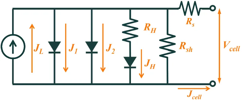
The circuit model includes the following components:
-
Light-generated current source (IL): Represents the photocurrent generated when light is absorbed in the solar cell. This current is proportional to the incident irradiance and depends on the cell’s quantum efficiency.
-
First diode (I01, m1): The primary diode component with saturation current I01 and ideality factor m1 ≈ 1. This is the fundamental component required in all equivalent circuit models. When reverse bias breakdown is enabled, the first diode also includes avalanche breakdown behaviour.
-
Second diode (I02, m2): An optional additional diode with saturation current I02 and ideality factor m2 ≈ 2. This component improves model accuracy for certain cell types, particularly when fitting IV curves with distinct curvature characteristics.
-
Resistive-limited enhanced recombination component (I0H, mH, RH): An optional advanced component with its own saturation current I0H, ideality factor mH, and series resistance RH. This component can improve fitting accuracy for complex IV curve behaviour.
-
Series resistance (Rs): Represents the sum of all resistive losses in the current path, including the bulk resistance of the semiconductor, contact resistance between metal and semiconductor, resistance of the metallic grid (fingers and busbars), and interconnection resistance. This resistance causes voltage-dependent power losses that are proportional to I².
-
Shunt resistance (Rsh): Represents leakage current paths that bypass the p-n junction.
-
Reverse bias breakdown (VB1, IB1): Optional inputs that model breakdown of the first diode under reverse bias. When a solar cell is driven to a sufficiently negative voltage—for example, when a cell is shaded while other cells in the string continue to produce current—the reverse current increases sharply. This is controlled by the breakdown voltage VB1 and the breakdown current density JB1. See Reverse bias breakdown below for the full equation.
Forward bias equation
Section titled “Forward bias equation”Under normal operating conditions (forward bias and moderate reverse bias above the breakdown threshold), the equivalent circuit produces an implicit current–voltage relationship. When all components are enabled, the full IV equation must be solved numerically:
where the current through the resistive-limited component is:
and the voltage across the H diode is:
Note that only the current IH flows through the resistance RH, not the total cell current I.
Reverse bias breakdown
Section titled “Reverse bias breakdown”When reverse bias breakdown is enabled, the first diode uses a reverse-breakdown current expression once the cell voltage is driven sufficiently negative. This provides a simple SPICE-style model for the rapid increase in reverse current during breakdown.
SunSolve implements the standard SPICE-style reverse-bias breakdown extension for the first diode, defined by a breakdown voltage parameter and a current parameter .
In the reverse-breakdown region, where , the diode current is:
where:
- is the diode current
- is the diode saturation current
- is the diode voltage
- is the diode ideality factor
- is the thermal voltage
- is the temperature-adjusted internal breakdown voltage used by the solver
For reverse voltages that are negative but not yet beyond the breakdown threshold, the solver uses a separate reverse-bias expression. The equation shown above applies only in the reverse-breakdown region.
The user specifies the reverse-breakdown parameters and . Internally, the solver computes the temperature-adjusted internal breakdown voltage from these parameters using:
is entered as a positive voltage magnitude; breakdown occurs when the diode voltage becomes more negative than approximately at the reference temperature. The solver converts the user input into a temperature-adjusted internal breakdown voltage, , which is then used in the reverse-bias diode equation.
Meaning of and
Section titled “Meaning of VBV_BVB and IBI_BIB”is the main parameter controlling where reverse breakdown begins.
- Larger moves breakdown to a more negative reverse voltage.
- Smaller brings breakdown in earlier.
is a secondary fitting parameter used internally when calculating the breakdown voltage used by the solver.
- In practice, changing usually causes a modest shift in the apparent breakdown knee.
- It does not usually produce a large change in the shape of the reverse IV curve.
In other words, mainly controls where reverse breakdown occurs, while has a more limited secondary effect through the internal mapping to .
Optional circuit components
Section titled “Optional circuit components”Voltage- and illumination-dependent loss component
Section titled “Voltage- and illumination-dependent loss component”Optionally, a voltage- and illumination-dependent recombination loss term may be included in the equivalent circuit. This component is primarily used for thin-film solar cells, particularly amorphous silicon (a-Si:H) and cadmium telluride (CdTe) devices, where photocurrent exhibits non-superposition behaviour and significant forward-bias roll-off.
When included this component replaces the resistance-limited enhanced recombination component.
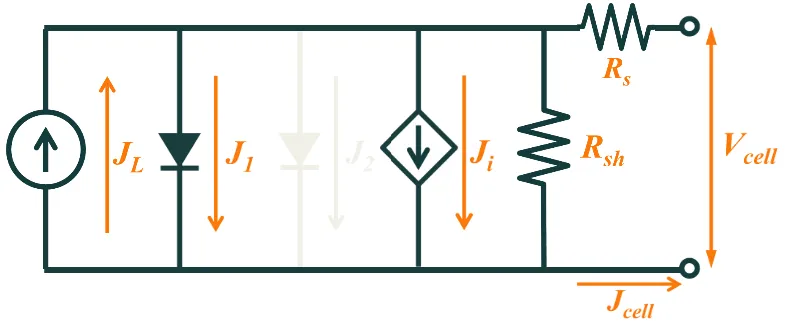
Equivalent circuit model with voltage- and illumination-dependent recombination loss component.
The loss current is given by:
Where is the light-generated current (linking the loss to illumination intensity), is a combined material parameter representing the i-layer thickness squared divided by the effective minority carrier mobility-lifetime product, Vbi is the built-in voltage, and V is the internal voltage across the diode junction (equal to Vterminal + IRs).
This term represents recombination losses that increase under both higher illumination (via IL) and forward bias (as the internal junction voltage V approaches Vbi). The denominator captures the reduction in internal electric field strength as forward bias reduces the effective depletion width.
When enabled, the full cell current–voltage equation becomes:
In the numerical implementation, smooth regularisation functions are applied near the singularity at V = Vbi to ensure robust convergence in the circuit solver (SunSolve uses a SPICE-based solver for all equivalent circuit calculations).
This component is typically disabled for crystalline silicon modules, where superposition holds and diode recombination dominates.
Note:
- In practice, the parameter is typically fitted to measured IV curves rather than calculated from the individual physical properties it represents.
- While this loss component was originally developed for a-Si devices, and the equation parameters reflect that origin, it has also been successfully applied to CdTe devices.
- The recombination current is numerically capped at 99% of IL to prevent unphysical solutions.
Assumptions and limitations
Section titled “Assumptions and limitations”The following aspects of the equivalent circuit model are worth remembering when designing modules:
-
Parameters are constant with voltage: This can be a poor representation of cells whose:
- Series resistance decreases significantly with increasing voltage (e.g., when contact resistance is significant)
- Carrier collection decreases with increasing voltage (e.g., as occurs in some rear-contact cells)
- Recombination varies with voltage (e.g., when the excess carrier concentration is not much less than or much greater than the bulk doping over the entire voltage range of interest)
-
Spatially uniform treatment: The equivalent circuit treats the solar cell as being spatially uniform. Cells with high spatial variability in material properties or current distribution may not be accurately represented by this lumped-parameter approach.
-
Parameter physical meaning: The IV curve of practically every solar cell can be well fitted by an equivalent circuit when there are sufficient adjustable parameters. A high coefficient of determination (R²) makes it appear as though the equivalent circuit is a good representation of the solar cell. However, are the best-fit values of the parameters physically meaningful? For example, if the best-fit value of m2 is 3.2, this may provide a good mathematical fit but may not correspond to a distinct physical recombination mechanism.
-
Temperature dependence: Although the model equations include temperature dependence through the thermal voltage VT = kT/q, remember that in real solar cells the value of practically every parameter (such as I01, I02, and Rs) also depends on temperature. Evaluating module performance across different temperatures requires appropriate temperature-dependent parameter values.
-
Series resistance variation: Series resistance determined from light IV curves can differ from that determined from dark IV curves, particularly when contact resistance or other non-ohmic effects are significant.
-
Breakdown model simplicity: The avalanche breakdown model uses a standard exponential approximation. Real breakdown behaviour can be more complex, involving localised hot spots and non-uniform current flow. The equivalent circuit treats breakdown as a bulk cell property, which may not capture spatially non-uniform breakdown effects.
Despite these limitations, the equivalent circuit model remains a valuable tool for module design when used with an understanding of its assumptions and appropriate parameter values for the cell technology being modelled.
Series resistance calculation
Section titled “Series resistance calculation”SunSolve offers two approaches for determining the series resistance Rs used in the equivalent circuit:
Option 1: Fixed series resistance value
The user provides a single value for Rs that applies to all cells. This approach is appropriate when electrodes are not explicitly modelled or when a simplified resistance model is sufficient.
Option 2: Analytical grid resistance calculation
The user provides the non-grid series resistance Rs,1 and SunSolve calculates the grid resistance Rs,2 analytically based on electrode geometry and material properties. The total series resistance is:
For more detail on how SunSolve calculates , see the Series resistance calculation page.