
Determining PVsyst bifacial inputs with SunSolve
SunSolve Yield provides a validated procedure for determining the bifacial input factors required for accurate PVsyst simulations. These factors capture the optical and electrical effects that PVsyst simplifies through its view-factor model.
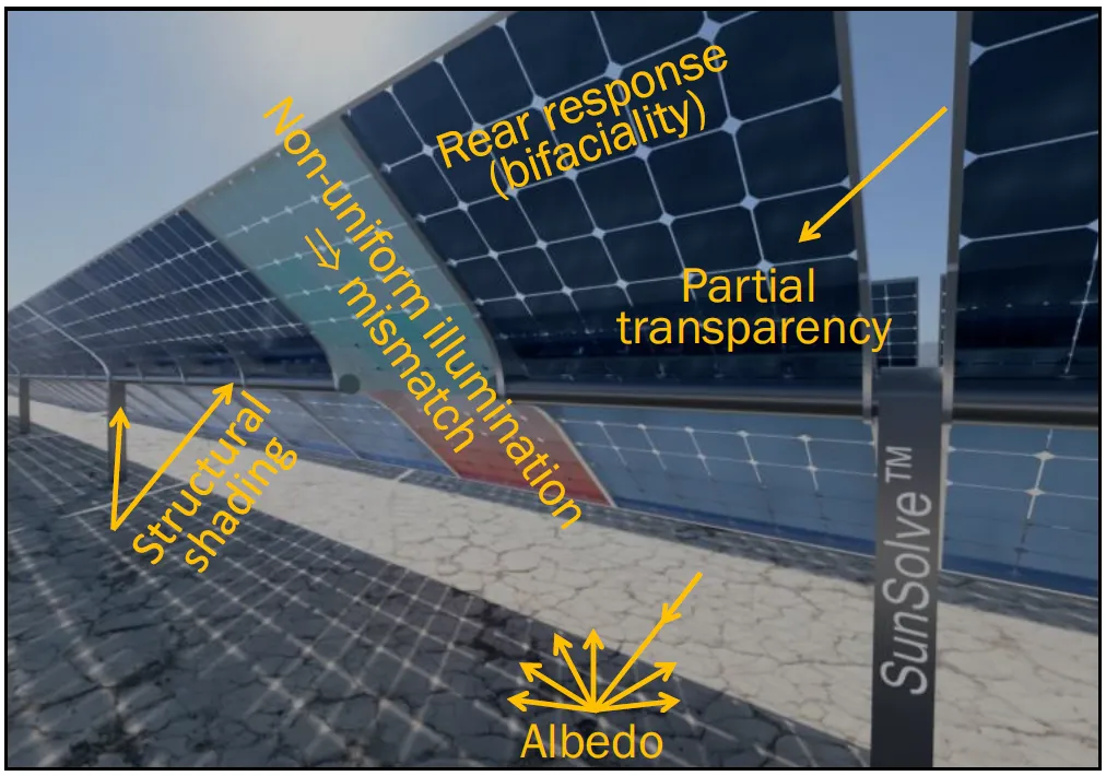
PVsyst represents the rear-side illumination of bifacial systems using five correction factors:
SunSolve computes these factors from seven controlled simulations that isolate each effect by modifying the system scene.
By comparing these results, SunSolve produces energy-weighted annual averages suitable for direct use in PVsyst.
The graphs below present example results, where the data points represent the weighted-average input for each day of a typical year under one particular set of conditions.
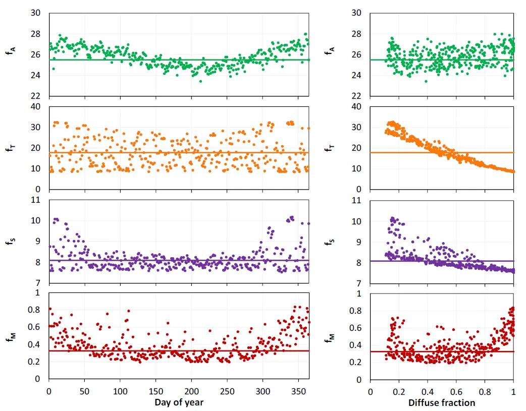 Example plot showing fA, fT, fS, and fM
varying with day of year and average daily diffuse fraction.
Example plot showing fA, fT, fS, and fM
varying with day of year and average daily diffuse fraction.
Method summary
Section link: Method summaryThere are two ways to calculate the factors with SunSolve — an automated approach (recommended for most users) and a manual approach for advanced or custom configurations not yet supported by automation.
A short walkthrough video demonstrating the recommended automated workflow is available here: Yield PVsyst Factor Automated Workflow — SunSolve.com A walkthrough video demonstrating the manual workflow is available here: Yield PVsyst Factor Manual Workflow — SunSolve.com
For a full description of the Analysis feature used to extract these factors, see:
- Analysis options — the inputs available on the Analysis tab.
- Analysis results — the outputs reported after an analysis.
- Analysis methodology — the controlled simulations and the equations behind each factor.
Using the results in PVsyst
Section link: Using the results in PVsystAfter running and analysing the simulations in SunSolve, perform the following steps in PVsyst:
- Set Ground albedo = fA
- Set Shed transparent factor = fT
- Set Structure shading factor = fS
- Set Rear mismatch factor = fMR
- Bifaciality factor = fB (PVsyst reads this from the module PAN file; see how SunSolve determines fB)
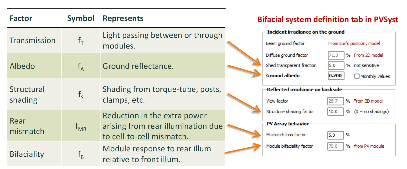 Screenshot of PVsyst (v7.4.6) showing
bifacial inputs and their explanations.
Screenshot of PVsyst (v7.4.6) showing
bifacial inputs and their explanations.
File downloads
Section link: File downloadsOriginal white paper
Section link: Original white paperInstructions on extracting PVsyst inputs with SunSolve (click to download)
This PDF is the original PV Lighthouse white paper that describes how to determine PVsyst bifacial inputs using SunSolve Yield. It lists assumptions, definitions, and derivations for each factor and includes example results. Much of that material is now incorporated into this help page.
Note that section 4 describes the manual method for calculating bifacial factors, which is now superseded by the automated approach.
The white paper covers the following topics:
- Desired PVsyst inputs: defines the five bifacial correction factors (fT, fA, fS, fMR, fB) and their PVsyst equivalents.
- Improvements to our previous methodology: describes changes from earlier versions, including support for PVsyst ≥ 7.4.6 and a correction to the fMR equation.
- General procedure: explains how six controlled simulations are combined to isolate each factor.
- Step-by-step instructions: walks through running the six simulations in SunSolve and loading results into the analysis spreadsheet.
- Examples: presents results for a 2P single-axis tracker and a 4L fixed-tilt system, with interpretation guidance.
- Derivations: provides full derivations for the equations in section 3.
- Comments for advanced users: discusses topics such as skipping simulations, effective albedo (fA), structural shading contributions, and mismatch factor subtleties.
Factor extraction spreadsheet (manual method)
Section link: Factor extraction spreadsheet (manual method)Spreadsheet for extraction of PVsyst inputs This spreadsheet contains the equations and plots needed to manually extract the PVsyst bifacial inputs, following the approach described in the white paper above.