Interfaces
Interfaces exist at the boundary between two slabs (or a slab and an electrode).
An interface is assigned with
- a surface morphology;
- an optical scattering model;
- and either a
- a stack of thin films, where each film has its own material and thickness; or
- a ‘reflector’ with a defined reflectance, absorbance and transmittance.
Read more about these features on the Texture tab, the Scattering tab and the Layers tab. The reflector can have properties that are either constant with wavelength or vary with wavelength.
Two-region interfaces
Section titled “Two-region interfaces”Interfaces between layers can be defined as having two regions.
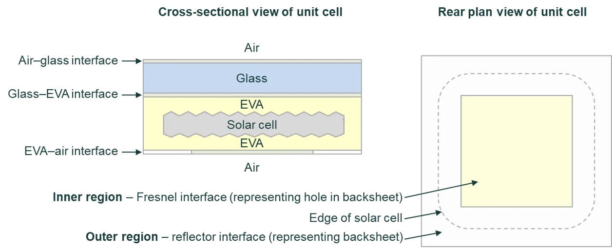
The figure below gives an example of when a two-region interface might be employed. It shows a bifacial solar cell encapsulated by EVA, where the backsheet contains square holes that allow light to reach the rear of the solar cell. Many bifacial modules have this structure. The outer region is defined as a reflector interface (representing a backsheet) and the inner region is defined as a Fresnel interface (representing a hole in the backsheet).
The outer region constitutes all of the unit-cell except the area inside the inner region. The shape of the inner region is centred on the unit cell. The interfaces associated with the solar cell itself cannot be defined with two regions.
If a two-region interface is used within a module, then the inputs for the outer region define the module’s perimeter as well as the outer region of each unit cell.
Dual interfaces
Section titled “Dual interfaces”Dual interfaces provide a flexible way to define complicated interfaces.
A dual interface is comprised of two possible interfaces, Interface A and Interface B, as well as a mixing function that defines the probability that an incident ray interacts with Interface A; otherwise it interacts with Interface B.
The mixing function can be a constant. E.g., if it equals 0.8, then 80% of rays that interact with the dual interface will be treated as interacting with Interface A, and 20% will be treated as interacting with Interface B. The mixing function can also be wavelength-dependent where the dependence follows the scalar-scattering function described on the Scattering tab.
The morphology of Interface A overlays the surface morphology.
Possible uses for a dual interface:
- Texture on texture: Simulate bumpy pyramids by setting the main surface morphology to pyramids, selecting a dual interface, setting the mixing function to 1 (so that Interface B is redundant), and setting the surface morphology of Interface A to spherical caps.
- Sporadic optical defects: Simulate an SiNₓ film covered by a splattering of unwanted silver particles (e.g., 4% coverage) by selecting a dual interface, setting the mixing function to 0.04, setting Interface A to have two films, Ag and SiNₓ, and setting Interface B to have just SiNₓ.