Surface morphology and texture
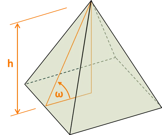
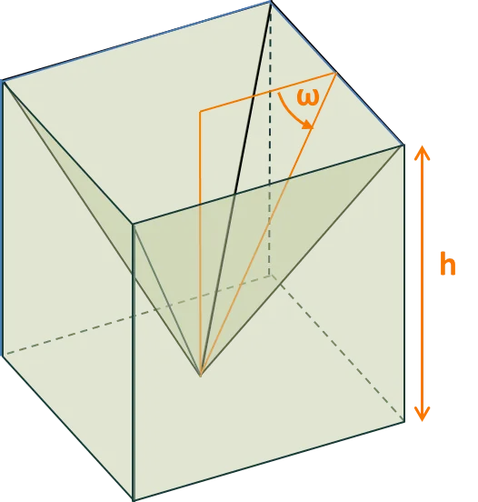
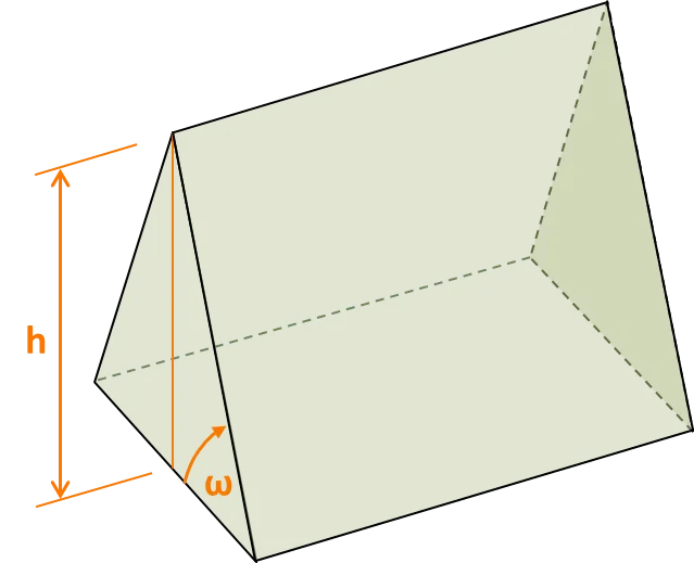
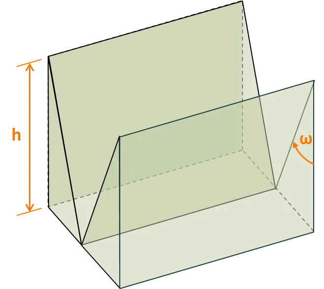
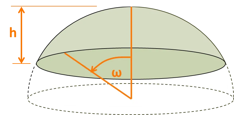
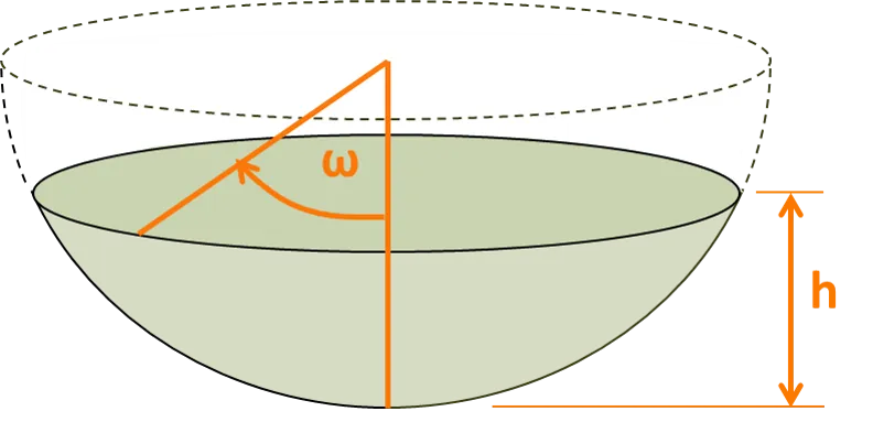
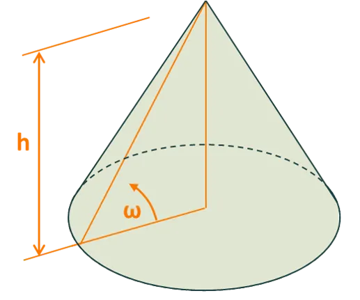
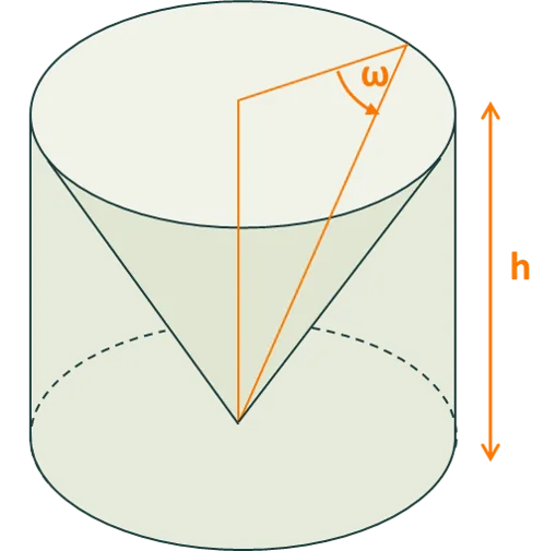
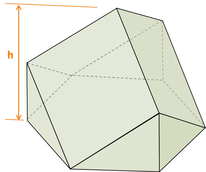
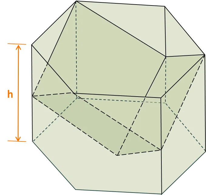
The surface morphology (i.e., the texture) of each interface can be set to one of several options. Images of the non-planar options are shown below, where the image depicts the feature that is repeated in the x and y directions over the entire interface. The user sets the angle , and the height or width of the surface feature.
Note that (i) a V groove extends across the entire x or y expanse of the interface, depending on whether the user selects an x or y orientation; and (ii) a corner cube, which is the basis for DSM’s ‘light-trapping film’, has a fixed and a regular hexagonal unit cell.
Available morphologies
Section titled “Available morphologies”Upright pyramid
Inverted pyramid
Upright V groove
Inverted V groove
Upright spherical cap
Inverted spherical cap
Upright cone
Inverted cone
Upright corner cube
Inverted corner cube
Vertical orientation
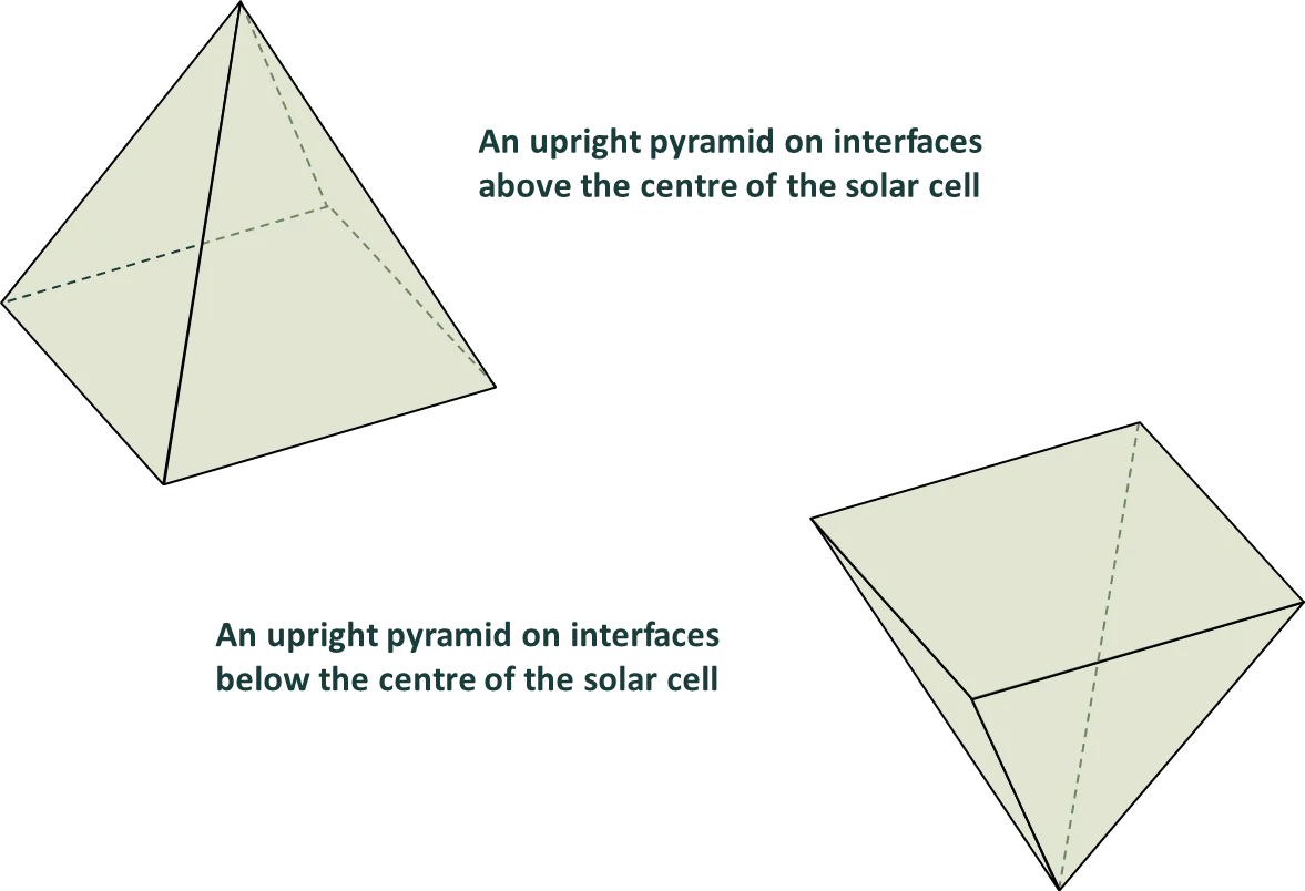
Section titled “Vertical orientation”The images above illustrate the vertical orientation for interfaces that lie above the centre of the solar cell.
The morphologies have the opposite orientation for interfaces that lie below the centre of the solar cell. That is, the morphologies are assumed to be upside-down at surfaces below the centre of the cell.
Random morphologies
Section titled “Random morphologies”The program provides the option to select either ‘random’ or ‘regular’ surface morphologies (i.e., texture). This helps simulate, for example, the ‘randomly’ oriented pyramids that cover the front surface of industrial monocrystalline silicon wafers, or the ‘regular’ inverted pyramids that have been employed in high-efficiency laboratory PERL solar cells.
The images below help explain how ‘random’ morphologies affect the propagation of rays in this program.
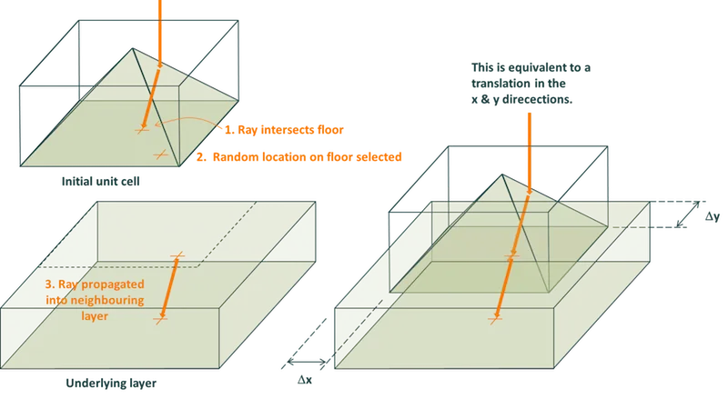
The simplest geometrical feature of a morphology (e.g., a pyramid or a groove) is bounded by the planes of its unit cell. A ray that intersects the wall of a unit cell is propagated into a neighbouring unit cell, whereas a ray that intersects the floor (or ceiling) of a unit cell is propagated into the layer below (or above) the feature. This might, for example, be the propagation of a ray from the textured region of a wafer to the bulk of the wafer.
The images below show how this propagation is achieved when a ‘random’ morphology is selected. They depict a ray intersecting (i) a wall and (ii) the floor of a unit cell. When the ray intersects one of these boundary planes, it is assigned a new random location on that boundary, and then the ray is propagated into the neighbouring unit cell (or layer) via the same location on the common boundary and with the same propagation angle. Thus, the features are not rotated but merely translated with respect to one another.
Ray intersecting the wall of a pyramid’s unit cell
Section titled “Ray intersecting the wall of a pyramid’s unit cell”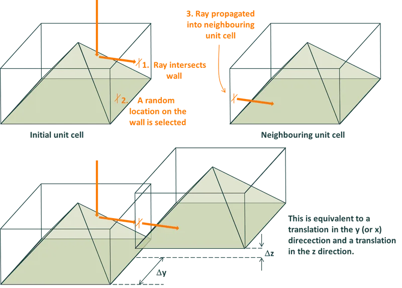
Ray intersecting the floor of a pyramid’s unit cell
Section titled “Ray intersecting the floor of a pyramid’s unit cell”