Module frames and brackets
Module frames can be added to both simple and complex modules. The frame is applied around the outside of the active area (i.e. the area that includes the cells, glass, EVA, backsheet). Adding a frame will increase the dimensions of the module in proportion to the frame size.
Frame and bracket geometry
Section titled “Frame and bracket geometry”The frame is defined by its width, height, and lip (frontside overhang) dimensions, while the bracket represents the mounting structure beneath or behind the module edge. Together, they form an L-shaped cross-section around the module, as shown in the figure below.
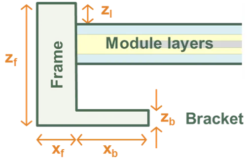
Frame and Bracket Definition, shown for the left edge of module.
Frame symmetry options
Section titled “Frame symmetry options”The frame and bracket can be configured using three symmetry options, which determine which input fields are displayed:
-
Symmetric: All four sides (left, right, top, bottom) have identical dimensions. This is the simplest option and is suitable for modules where the frame is uniform on all edges.
-
Half-symmetric: Two opposing sides share the same dimensions. The left and right edges have dimension , while the top and bottom edges have dimension . This is commonly used for rectangular modules where the long edges differ from the short edges.
-
Asymmetric: Each edge can be independently defined with its own dimensions (, , , ). This provides maximum flexibility for modules with non-standard frame designs.
The symmetry option is selected from the Frame symmetry dropdown in the user interface. Changing this option will update which input fields are displayed.
Coordinate system and edge numbering
Section titled “Coordinate system and edge numbering”The frame and bracket dimensions use a consistent coordinate system:
- X-direction: Left-right (horizontal when viewing the module from the front)
- Y-direction: Bottom-top (vertical when viewing the module from the front)
- Z-direction: Perpendicular to the module surface (height/depth)
For asymmetric configurations, the subscript numbering follows this convention:
- Subscript 1: Left edge () or Bottom edge ()
- Subscript 2: Right edge () or Top edge ()
Frame dimensions
Section titled “Frame dimensions”The frame dimensions define the outer structure that surrounds the active area of the module. All dimensions are measured from the edge of the active area.
Frame width/thickness
Section titled “Frame width/thickness”The horizontal width of the frame depends on the selected symmetry option:
| Symmetry | Input field | Symbol | Description |
|---|---|---|---|
| Symmetric | Width | Single value applied to all four edges (left, right, top, bottom) | |
| Half-symmetric | Left/right | Width of the left and right frame edges | |
| Top/bottom | Width of the top and bottom frame edges | ||
| Asymmetric | Left | Width of the left frame edge | |
| Right | Width of the right frame edge | ||
| Bottom | Width of the bottom frame edge | ||
| Top | Width of the top frame edge |
Typical frame widths range from 8–15 mm depending on module size and manufacturer.
Frame height
Section titled “Frame height”Height (): The vertical height of the frame measured perpendicular to the module surface. This is common to all symmetry options. Typical values are 30–40 mm, with 35 mm being most common.
Constraint: The frame height must be large enough to accommodate the bracket height, the module layer thickness (excluding the frame), and the lip height. Specifically:
where is the combined thickness of the module layers (glass, encapsulant, cells, backsheet). SunSolve will display a warning if this constraint is violated.
Frame lip
Section titled “Frame lip”Lip (): The height of the frame portion that extends over the module glass surface. This overhang protects the edge of the glass and provides weather sealing. This is common to all symmetry options. Typical values are 0–2 mm, with 2 mm being common.
Bracket dimensions
Section titled “Bracket dimensions”The bracket dimensions define the mounting structure that extends inward from the inner edge of the frame, beneath or behind the module. Brackets represent the section of the frame used to attach the module to the racking system.
Removing brackets: To simulate modules without mounting brackets, set all bracket dimensions (width and height) to zero.
Bracket width/extent
Section titled “Bracket width/extent”The horizontal extent of the bracket (measured from the inner edge of the frame toward the centre of the module) depends on the selected symmetry option:
| Symmetry | Input field | Symbol | Description |
|---|---|---|---|
| Symmetric | Width | Single value applied to all four edges | |
| Half-symmetric | Left/right | Bracket extent on left and right edges | |
| Top/bottom | Bracket extent on top and bottom edges | ||
| Asymmetric | Left width | Bracket extent on left edge | |
| Right width | Bracket extent on right edge | ||
| Bottom width | Bracket extent on bottom edge | ||
| Top width | Bracket extent on top edge |
Bracket dimensions typically range from 5–25 mm depending on the mounting system. Modules often have larger brackets on the long edges (where mounting clamps attach) and smaller or no brackets on the short edges.
Constraint: Each bracket width must be less than half the corresponding module dimension (measured without the frame). For example, for a half-symmetric configuration:
where and are the module width and length without the frame. SunSolve will display a warning if this constraint is violated.
Bracket height
Section titled “Bracket height”Height (): The thickness of the bracket measured perpendicular to the module surface. This is common to all symmetry options. Typical values are 1–3 mm, with 2 mm being common.
Important: The bracket height is independent of the frame height. The bracket height specifies only the thickness of the mounting bracket itself. The total frame height () must be set separately and must be large enough to accommodate the bracket height, module layers, and frame lip (see constraint under Frame height above).
Defining a frame in SunSolve Yield
Section titled “Defining a frame in SunSolve Yield”Frames can be added to any module during the loading process at the Optical Inputs step.
Enabling the frame
Section titled “Enabling the frame”- Navigate to the Frame tab in the Optical Inputs section
- Check the Include frame checkbox to enable frame inputs
- Select the appropriate Frame symmetry option from the dropdown:
- Choose Symmetric for modules with identical frame dimensions on all four edges
- Choose Half-symmetric for rectangular modules where long edges differ from short edges (most common)
- Choose Asymmetric for modules with unique frame dimensions on each edge
- Enter the frame and bracket dimensions as described in the sections above
- Configure the Frame material to define the optical properties of the frame surface
Frame symmetry examples
Section titled “Frame symmetry examples”The three screenshots below show how the input fields change based on the selected symmetry option:
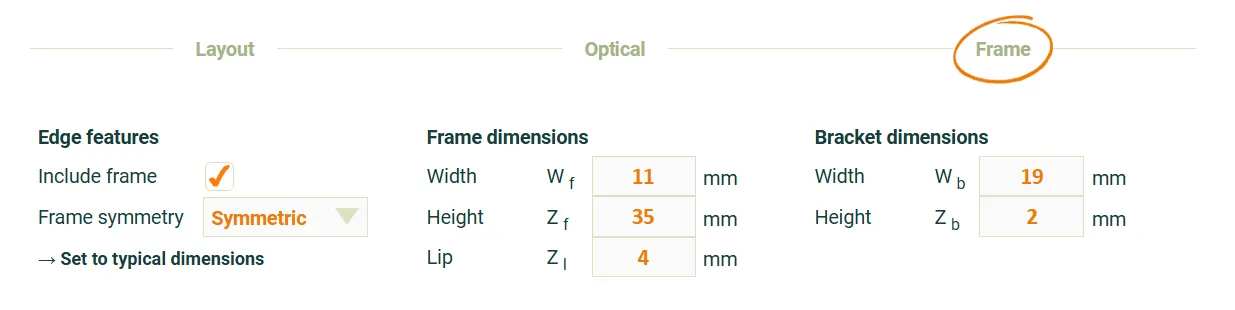 Symmetric frame configuration: Single width value applies to all four edges.
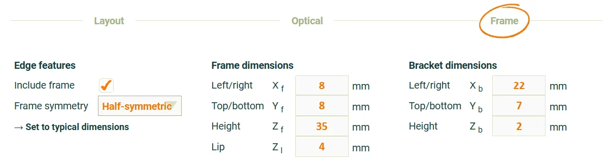 Half-symmetric frame configuration: for left/right edges, for top/bottom edges.
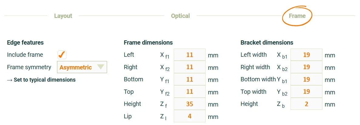 Asymmetric frame configuration: Each edge has independent frame and bracket dimensions.
Choosing the right symmetry option
Section titled “Choosing the right symmetry option”- Use Symmetric when the frame is uniform on all sides (typical for older modules)
- Use Half-symmetric (most common) when the module is rectangular and the long edges have different frame/bracket dimensions than the short edges
- Use Asymmetric when the frame design is non-standard with different dimensions on each edge
Frame material
Section titled “Frame material”The frame material defines the optical properties of the frame surface, including reflection, absorption, and scattering characteristics. These properties affect how light interacts with the frame during ray tracing simulations.
Default material: Anodized aluminium alloy is the default and most common frame material for solar modules. The optical data in SunSolve represents a typical silver/grey coloured anodised aluminium alloy frame material sourced from the solar industry in 2019 and measured at UNSW using a spectrophotometer (Perkin Elmer 1050) with 150 mm diameter integrating sphere under air.
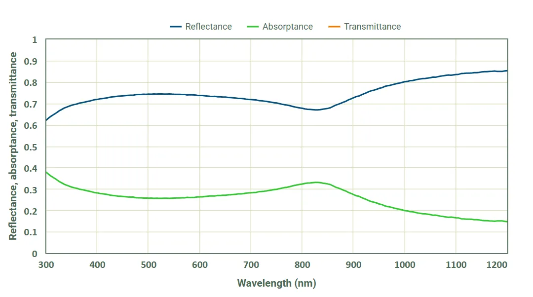 Spectral reflectance and absorptance of the default anodised aluminium alloy frame material.
Optical behaviour: The frame material definition specifies the surface optical properties of the frame. During ray tracing, light rays that strike the frame surface are reflected, or absorbed, according to the material’s optical properties. The frame is treated as opaque—no light is transmitted through the frame material itself.
By default the scattering is set to use a Lambertian distribution with a scattering fraction of 50% (i.e. half the reflected light is scattered).
Selecting frame material
Section titled “Selecting frame material”To configure the frame material in SunSolve Yield:
- Navigate to the Frame tab in the Optical Inputs section
- Ensure Include frame is checked
- In the Frame material section, select a material from the dropdown menu:
- The default selection is “Anodized aluminum alloy”
- To configure the details select “Custom”
- Click → Show details to expand the material properties panel and view:
- Scattering distribution settings
- Scattering fraction controls
- An option to switch between a reflector and a material (→ Switch from reflector to Fresnel)
- Inputs to select and define the reflector or material
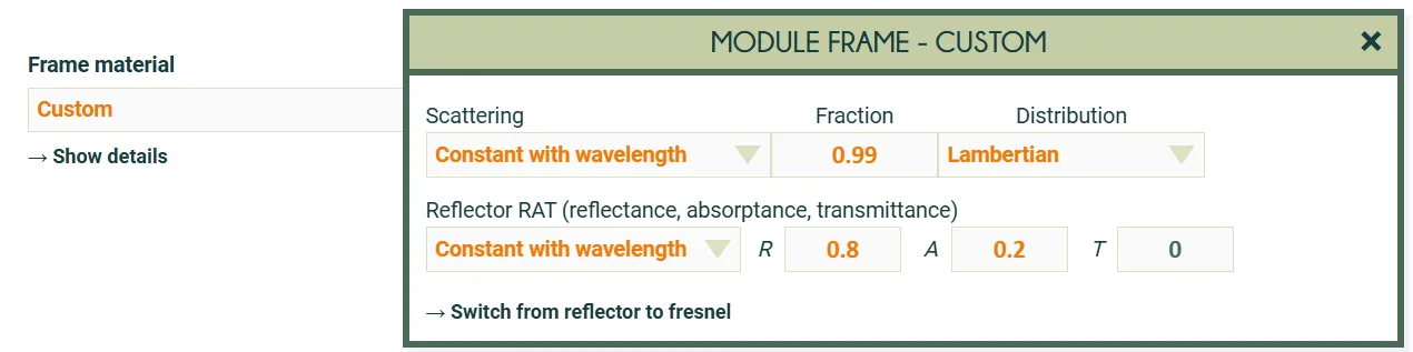 Screenshot of the inputs used to define a custom optical interface for the frame.
In this example it is set to 99% lambertian scattering and a fixed reflectance of 80%.
Screenshot of the inputs used to define a custom optical interface for the frame.
In this example it is set to 99% lambertian scattering and a fixed reflectance of 80%.
Adding frames to simple modules
Section titled “Adding frames to simple modules”If you add a frame to a module loaded from a PAN file, it may be necessary to reduce the ‘Thickness’ on the ‘Layout’ tab. When a frame is included, this thickness refers to the thickness of the module layers excluding the frame. E.g., set the thickness to about 4.5 mm for a conventional glass-glass module.