System dimensions
For Fixed and Single-axis Tracker systems, SunSolve Yield provides two methods for defining system dimensions. Both methods define the same physical layout but use different input parameters to accommodate different user preferences and workflows. Waves systems use a different dimension definition method based on peak and trough separations. See the Waves system layout page for details.
Dimension definition methods
Section titled “Dimension definition methods”The ‘Options’ tab provides two ways of defining the system dimensions:
-
XY Axis - everything is defined in an XY space which matches the definition of XY from the module. This is the most flexible and generic way to define the system although some users may find it complex at first.
-
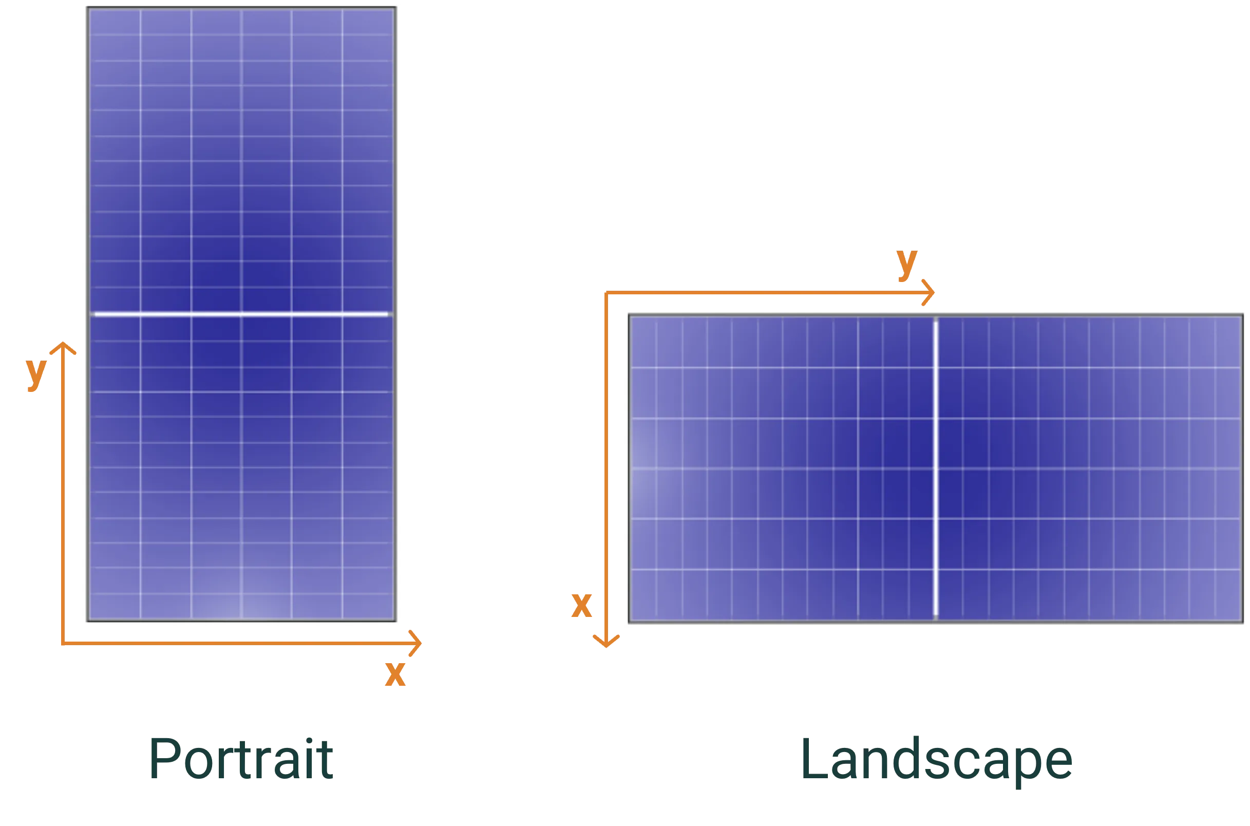
Landscape/portrait - a simplified set of dimensions that assume that the module is defined such that the X axis is the shorter side (i.e., the module appears as it would in a datasheet).
For most users, the Landscape/Portrait definition method provides a more intuitive interface, while the XY Axis method offers maximum flexibility for unconventional layouts.
Unit system concept
Section titled “Unit system concept”All system dimensions in SunSolve Yield are based on the concept of a unit system - a representative section of the PV array that is repeated infinitely in all directions. By simulating a unit system rather than an entire array, SunSolve can accurately model the behavior of modules in the interior of large installations while minimizing computational requirements.
The unit system contains:
- One or more modules arranged in a specific pattern
- Spacing between modules (module separation)
- Spacing between groups of modules (unit-system spacing)
- The structural components that support the modules
The unit system is then repeated infinitely in both horizontal directions, creating a representation of a large PV installation without edge effects.
XY Axis definition
Section titled “XY Axis definition”Overview
Section titled “Overview”In the XY Axis method, all dimensions are defined using X and Y coordinates that match the module’s coordinate system. This provides maximum flexibility for defining system layouts with any orientation.
Key parameters
Section titled “Key parameters”The XY Axis method uses the following parameters:
- XMS and YMS: Module separation - the spacing between adjacent modules
- XS and YS: Unit system pitch - the full extent (or pitch) of the unit system
- XSS and YSS: Unit system spacing - the spacing between groups of modules within a unit system
The unit-system spacing (XSS, YSS) is in addition to the module separation (XMS, YMS).
Configuration options
Section titled “Configuration options”When defining the unit-system dimensions, you have three options:
- Define the pitch: Specify XS and YS directly
- Define the spacing: Specify XSS and YSS directly
- Define row pitch and lateral spacing: If the tilt orientation of the modules is in the X direction, the row pitch is equivalent to XS and the lateral spacing is equivalent to YSS; whereas if the tilt orientation is in the Y direction, the row pitch is YS and the lateral spacing is XSS
Visual explanation
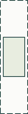
Section titled “Visual explanation”The first figure below defines the dimensions of the ‘unit system’ as well as the spacing between modules XMS and YMS. The dimensions XS and YS define the full extent (or pitch) of the unit system, whereas XSS and YSS define the spacing between groups of modules within a unit system.
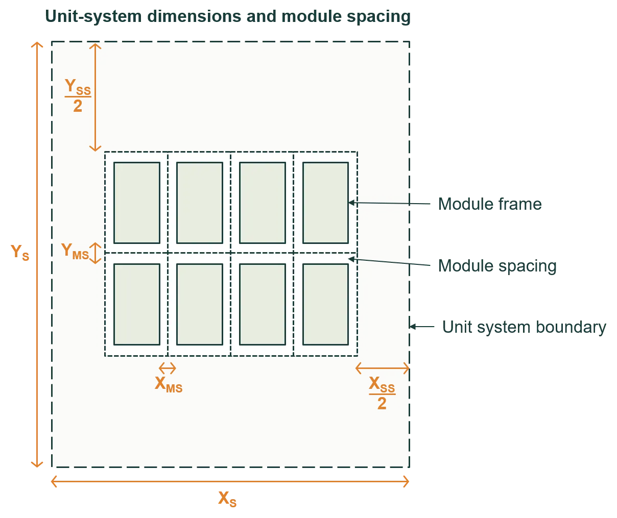
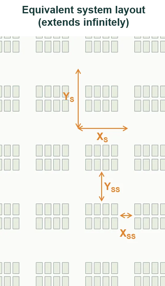
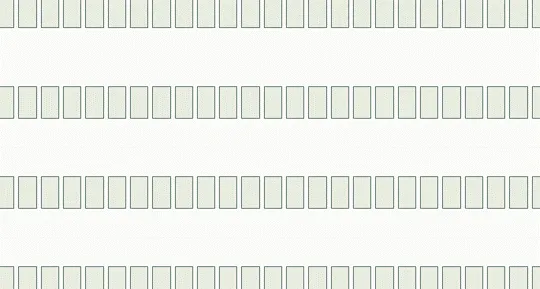
The second figure shows the layout of a system when it’s represented by the unit system of the first figure. The system contains infinitely many unit systems – which in this example contains 2 × 4 modules – and therefore it extends infinitely in both X and Y directions.
Landscape/portrait definition
Section titled “Landscape/portrait definition”Overview
Section titled “Overview”The Landscape/Portrait method is intended to simplify the inputs for the most common system and module configurations. It assumes that the module cell layout is defined with the X axis as the shorter side (i.e., the module appears as it would in a datasheet).
Key parameters
Section titled “Key parameters”The Landscape/Portrait method uses simplified terminology:
- Row pitch: The distance between corresponding points on adjacent rows (measured in the tilt direction)
- Lateral spacing: The spacing perpendicular to the rows
- Module separation: The spacing between individual modules
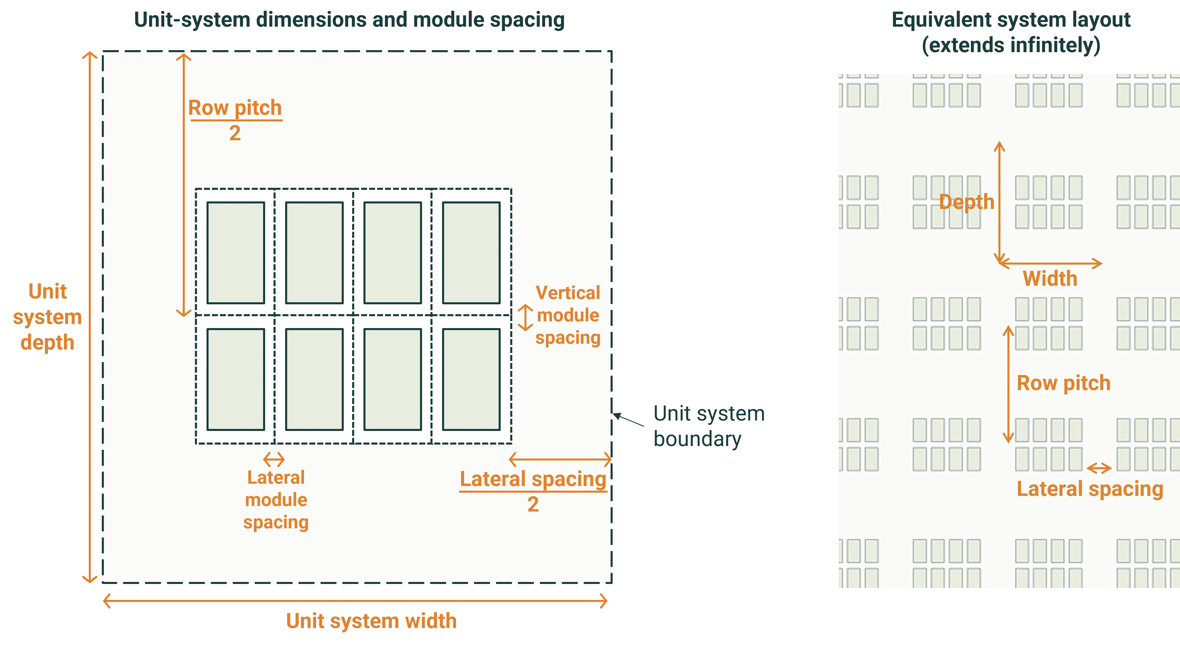
The dimensions of the unit-system are defined by the row pitch and lateral spacing, noting that the lateral module separation is included in the unit-system width.
Visual explanation
Section titled “Visual explanation”The figure below defines the dimensions of the ‘unit system’ as well as the lateral and vertical spacing between modules. The system contains infinitely many unit systems – which in this example contains 2 × 4 modules – and therefore it extends infinitely in both directions.
Simulating a central module
Section titled “Simulating a central module”For a large PV system – e.g., a system with hundreds of modules – we’re most interested in the performance of a central module. A central module is a module that’s sufficiently far from all sides of the system that it’s unaffected by edge effects.
Edge effects tend to be significant in:
- The first and last row of a system
- The five modules at either end of a row
Configuration for central module
Section titled “Configuration for central module”To simulate a central module:
- Configure a unit system with a single module
- Set module spacing to zero
- Set appropriate unit-system dimensions to represent the surrounding array
The figures below show an example unit system (left) and its equivalent system (right), which extends infinitely in X and Y directions.
This configuration ensures that the simulated module experiences the same shading and reflection patterns as a module deep within a large array, without the computational cost of simulating the entire system.