Fixed system layout
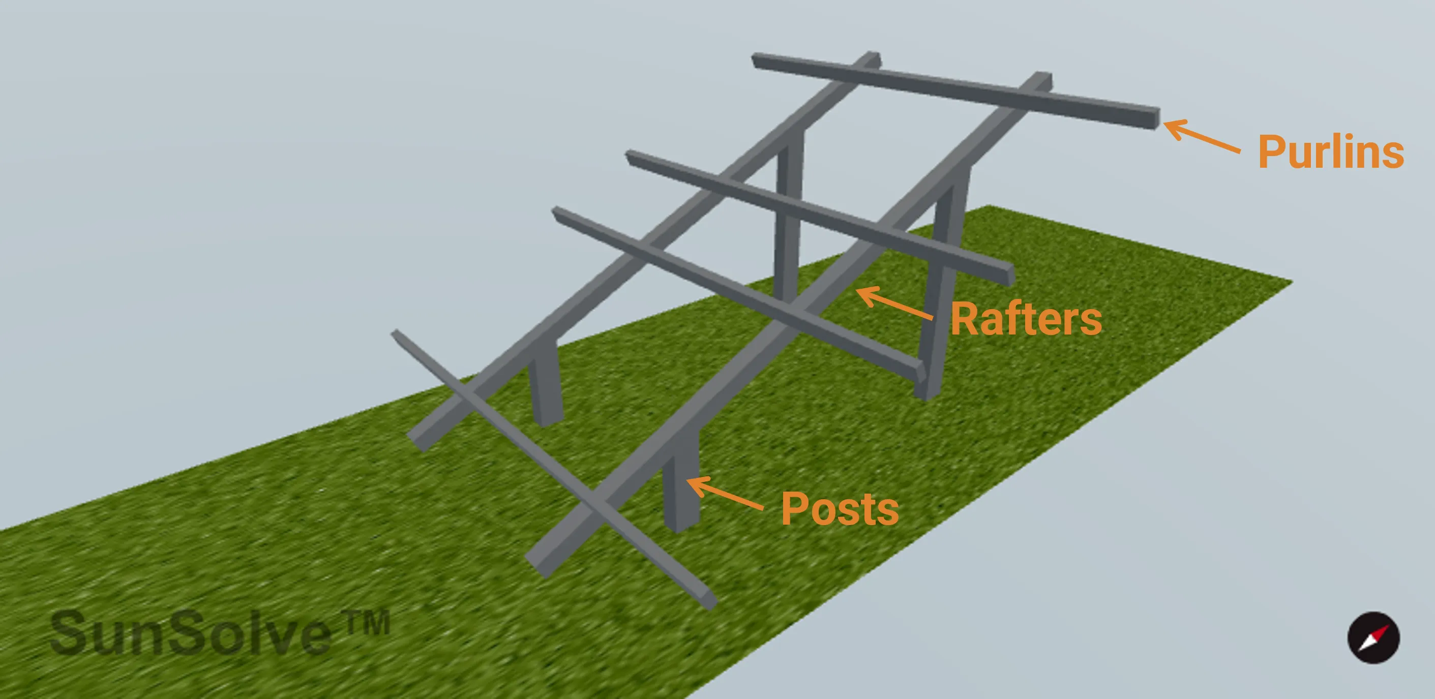
Fixed systems have modules mounted at a single tilt angle and azimuth. The structural components consist of posts, rafters, and purlins that support the modules in a stationary configuration.
System dimensions
Section titled “System dimensions”Fixed systems use the standard XY Axis or Landscape/Portrait dimension definition methods. These methods define how modules are arranged in the array and the spacing between them.
See the System Dimensions - XY and Landscape/Portrait page.
System components
Section titled “System components”Fixed systems are defined by purlins, rafters and posts. Modules are positioned on top of the purlins (or on top of the rafters if no purlins are used). Purlins are positioned on top of the rafters with no gap between them. Posts are attached to the rafters.
Edge handling for structural elements
Section titled “Edge handling for structural elements”When structural elements (purlins, rafters, or posts) are positioned such that their width (the cross-sectional dimension perpendicular to their length) would extend beyond the unit system boundary, they are automatically rendered as half-width elements positioned flush with the boundary. This ensures proper tiling when unit systems repeat infinitely without gaps or overlaps.
How it works:
- The element’s orientation determines which unit system boundary is checked (X or Y axis)
- The system detects when an element’s position along that axis would cause its width to extend past the boundary
- For circular cross-sections, a half-cylinder is created (semi-circular profile)
- For rectangular cross-sections, the width (perpendicular to length) is halved
- The element is positioned so its flat edge aligns with the unit system boundary
- The length remains unchanged - the “Match module group dimension” setting ensures length is properly sized to fit within the appropriate boundary, or custom lengths are assumed to fit
This automatic behavior applies to elements whose position places them at boundaries:
- Purlins in “Between modules” alignment mode (first and last purlins may be at edges)
- Rafters where number and pitch result in rafters at unit system edges
- Posts where layout and spacing result in posts at unit system edges
Note: Custom length values are not validated against system boundaries. Use “Match module group dimension” to ensure elements fit correctly.
Purlins
Section titled “Purlins”Purlins are structural members that provide immediate support for the modules. They are mounted on top of the rafters (or can be omitted if modules mount directly to rafters).
Cross section
Section titled “Cross section”The shape of the purlin in cross-section:
- Rectangular: Defined by width and depth dimensions
- Circular: Defined by diameter
Orientation
Section titled “Orientation”Direction the purlin runs relative to the module array:
- Horizontal: Runs parallel to the row axis (perpendicular to tilt direction)
- Vertical: Runs parallel to the tilt direction (perpendicular to row axis)
Length setting
Section titled “Length setting”Controls how the purlin length is determined:
- Match module group dimension: Automatically sets length to span the full module group width in the purlin’s orientation direction
- Custom: Manually specify the purlin length
When using “Match module group dimension”, the length automatically adjusts based on orientation:
- Horizontal orientation → length matches total module group width along row axis
- Vertical orientation → length matches total module group width perpendicular to row axis
Alignment
Section titled “Alignment”Controls where purlins are positioned relative to the modules. This is a critical setting that determines the number and placement of purlins:
Centre of modules
- Multiple purlins positioned within each module
- You specify the Number of purlins per module and the Pitch (spacing) between them
- Purlins are centered within each module’s footprint
Edges of modules
- Two purlins per module, positioned at the module edges
- One purlin at each edge provides support
- Number and pitch inputs are hidden (automatically 2 purlins with module dimension as pitch)
Between modules
- Purlins positioned in the gaps between adjacent modules
- Number of purlins equals number of modules + 1
- Automatically accounts for module separation gaps
Dimensional parameters
Section titled “Dimensional parameters”- Width (Wprl): For rectangular cross-sections, the dimension perpendicular to the purlin length
- Depth (Dprl): For rectangular cross-sections, the vertical dimension
- Diameter (Dprl): For circular cross-sections
- Dist below (Zprl): Vertical distance from the bottom of the module group to the top of the purlin
- Length (Lprl): Only visible when Length setting is “Custom”
- Number (Nprl): Number of purlins per module (only for “Centre of modules” alignment)
- Pitch (Pprl): Center-to-center spacing between purlins (only for “Centre of modules” alignment, only visible when Number > 1)
Rafters
Section titled “Rafters”Rafters are the primary structural members that span the module group and support the purlins. Posts attach to the rafters to provide vertical support.
Cross section
Section titled “Cross section”The shape of the rafter in cross-section:
- Rectangular: Defined by width and depth dimensions
- Circular: Defined by diameter
Orientation
Section titled “Orientation”Direction the rafter runs relative to the module array:
- Horizontal: Runs parallel to the row axis
- Vertical: Runs perpendicular to the row axis (typical orientation)
The orientation affects how rafters interact with posts and how their length is calculated when using auto-sizing.
Length setting
Section titled “Length setting”Controls how the rafter length is determined:
- Match module group dimension: Automatically sets length to span the full module group width in the rafter’s orientation direction
- Custom: Manually specify the rafter length
When using “Match module group dimension”:
- Horizontal orientation → length matches total module group width along row axis
- Vertical orientation → length matches total module group width perpendicular to row axis
Rafter spacing
Section titled “Rafter spacing”Rafters are distributed across the system based on:
- Number (NR): Total number of rafters in the unit system
- Pitch (PR): Center-to-center spacing between rafter centerlines
The rafters are evenly spaced with the first and last rafters positioned symmetrically from the system center.
Dimensional parameters
Section titled “Dimensional parameters”- Width (WR): For rectangular cross-sections, measured perpendicular to rafter length
- Depth (DR): For rectangular cross-sections, the vertical dimension
- Diameter (DR): For circular cross-sections
- Length (LR): Only visible when Length setting is “Custom”
Posts are vertical support structures that attach to the rafters and transfer loads to the ground. Posts are only available in fixed systems when rafters are enabled.
Cross section
Section titled “Cross section”The shape of the post in cross-section:
- Rectangular: Defined by X and Y dimensions
- Circular: Defined by diameter
Top shape
Section titled “Top shape”The geometry of the post top (cap):
- Flat: Simple flat-top post with no cap
- Arch: Arched cap (half-cylinder shape)
- Hemispherical: Dome-shaped cap (half-sphere)
The top shape affects the visual appearance and can impact ray tracing for light reflected off the post top.
Post positioning
Section titled “Post positioning”Posts align with the rafter positions in one direction. In the perpendicular direction, positioning is controlled by:
Layout
- Central: Posts distributed along the rafter with user-defined spacing
- Edge: Posts positioned only at the edges (two posts per rafter)
For Central layout:
- Number (Npost): Number of posts per module group
- Pitch (Ppost): Center-to-center spacing between posts along the rafter
- Offset from center: Fine-tunes post position along the rafter, measured from the rafter center
Post height calculation
Section titled “Post height calculation”Post height is automatically calculated based on:
- Module group height above ground
- Distance from top of post to bottom of panel
- Rafter and purlin thicknesses
- System tilt angle (for posts not at system center, height adjusts to account for sloped modules)
Dist below module: Vertical gap between the top of the post and the bottom of the module group.
Dimensional parameters
Section titled “Dimensional parameters”- X dimension: For rectangular cross-sections (typically oriented along rafter)
- Y dimension: For rectangular cross-sections (typically oriented perpendicular to rafter)
- Diameter: For circular cross-sections