Single-axis tracker system layout
Single-axis tracking systems feature modules that rotate about an axis to follow the sun throughout the day, maximizing energy capture. The structure includes posts, torque tubes, clamps, and rails.
System dimensions
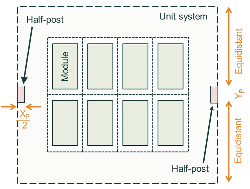
Section titled “System dimensions”Single-axis tracker systems use the standard XY Axis or Landscape/Portrait dimension definition methods. These methods define how modules are arranged in the array and the spacing between them.
See the System Dimensions page.
Module layout: Single bay vs. multiple bays
Section titled “Module layout: Single bay vs. multiple bays”The Module Layout setting allows you to define how modules are arranged along the tracker’s rotation axis. This affects shading, mechanical structure, and overall system design.
Single Bay
Section titled “Single Bay”In a Single Bay configuration, all modules in a row are part of a single continuous section.
- The total number of lateral modules defines how many modules are repeated laterally along the rotation axis.
- There are no gaps or separations between groups of modules along the tracker. Note that the lateral separation is applied between every module as described on the System Dimensions page.
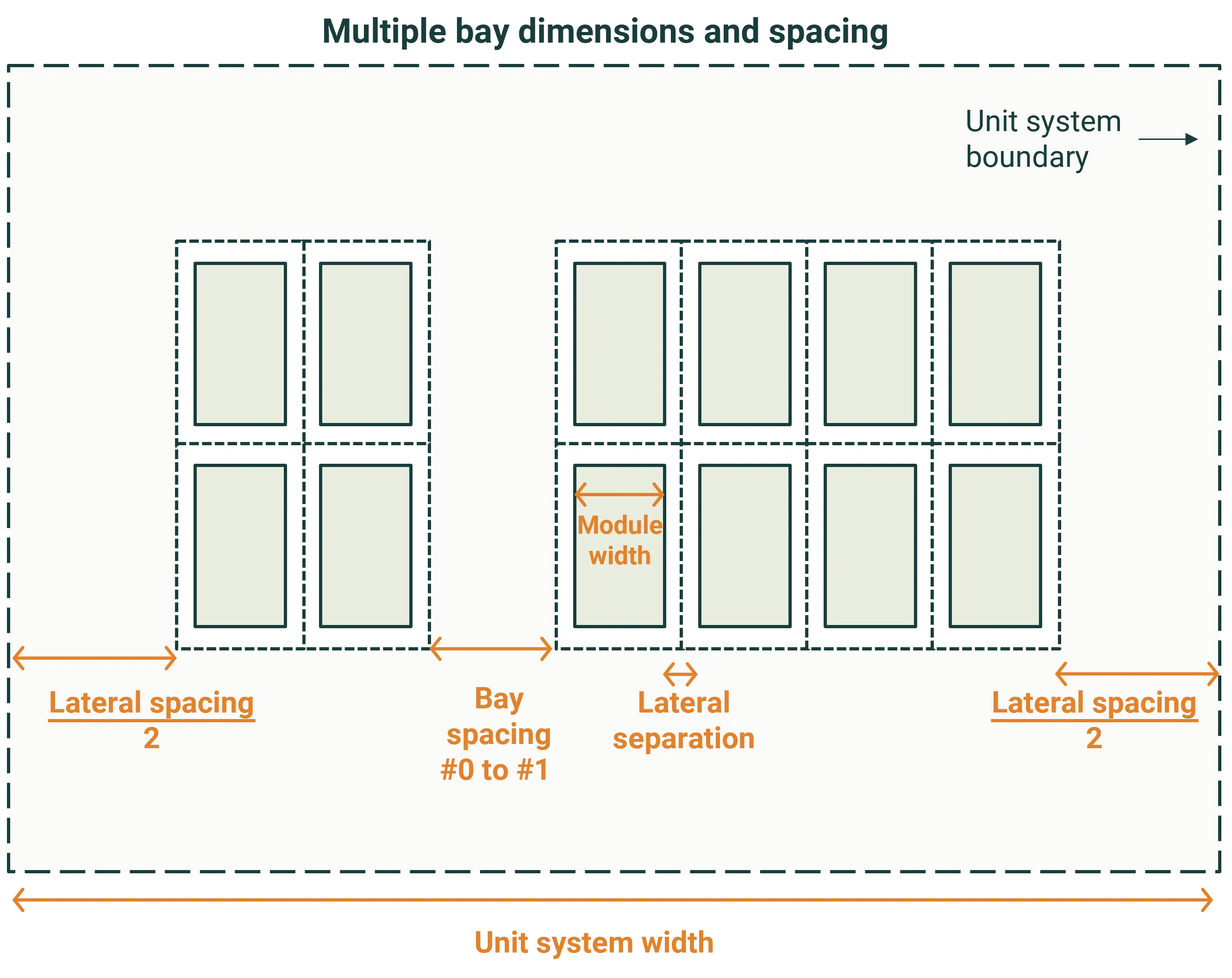
Multiple Bays
Section titled “Multiple Bays”In a Multiple Bays configuration, the tracker row is divided into multiple sections (bays), with gaps between them.
You define:
- The number of bays per tracker (1-10 bays)
- How many modules per bay along the row axis. Each bay can have a different number of modules (1-200 modules per bay), providing flexibility for non-uniform tracker designs. The total number of modules in each bay will be multiplied by the number of modules in the vertical direction.
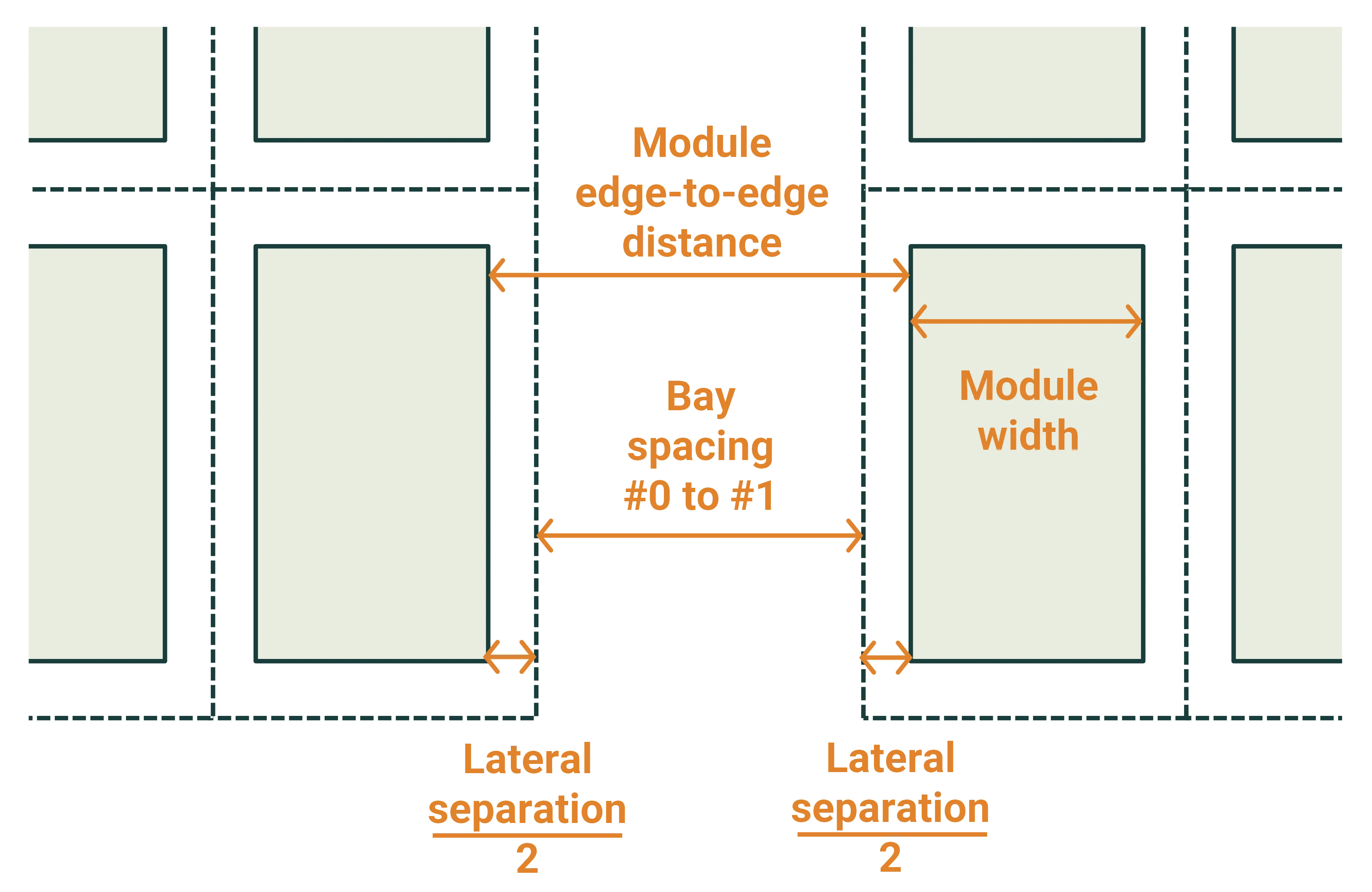
- Spacing between bays: The gap between adjacent bays along the tracker axis. This is an “internal” spacing applied between bays, not at the outer edges. The total module edge-to-edge distance is the bay spacing plus the lateral separation of the modules.
Note that the bay spacing is applied to the optical model but is not currently used in the simplified thermal model.
The images below illustrate an example where the number of bays is set to two. One bay containing two modules per bay and the other containing four modules per bay.
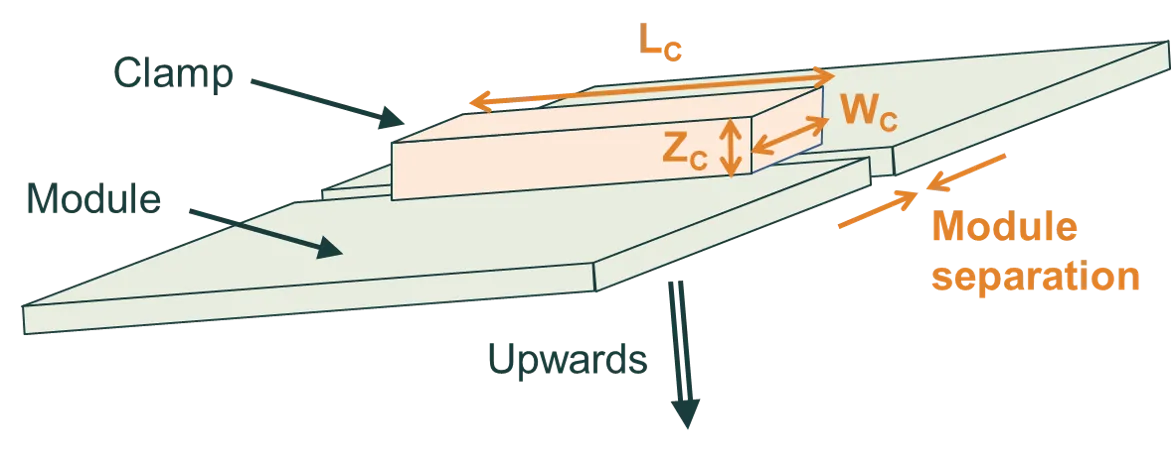
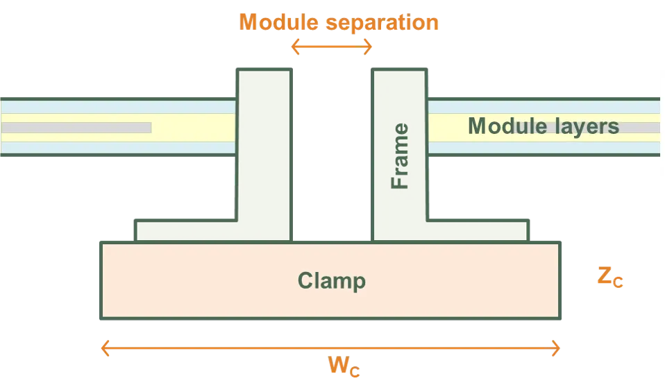
Clamps
Section titled “Clamps”Clamps are used to secure modules to the tracking structure. SunSolve treats clamps as rectangular prisms.
Positioning
Section titled “Positioning”The clamps lie immediately below the module frame (or immediately below the module layers if there is no frame). In the XY plane, the centre of the clamp coincides with the centre of the module separation. Two clamps are created per module.
Clamps do not protrude beyond the module spacing into the space surrounding a module row.
Dimensional parameters
Section titled “Dimensional parameters”The figures below define the clamp dimensions:
- Length (LC): Length of clamp along module sides
- Width (WC): Width of clamp perpendicular to module sides
- Height (ZC): Vertical thickness of clamp
Validation constraints
Section titled “Validation constraints”Clamp dimensions must satisfy the following constraints:
- Clamp length must be ≤ module group length (varies based on tilt orientation)
- Clamp width must be ≤ module width + module separation
- Clamp height must be < min(ZMT, ZMP, ZMG) (see Height definitions below)
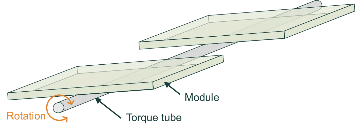
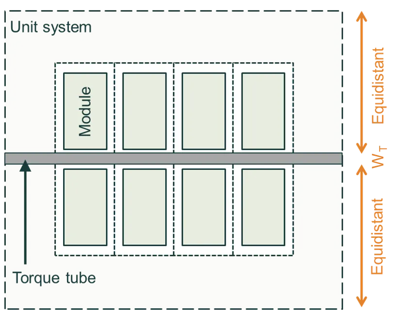
Torque tube
Section titled “Torque tube”The modules of a single-axis tracking system are mounted on a torque tube, which rotates as the sun passes through the sky. The figure below illustrates a single-axis tracking 1P system with a cylindrical torque tube; ‘1P’ stands for one module in portrait.
Cross section
Section titled “Cross section”The shape of the torque tube in cross-section:
- Circular: Defined by diameter
- Rectangular: Defined by width and height dimensions
- Hexagonal: Defined by inner diameter (inscribed circle)
- Octagonal: Defined by inner diameter (inscribed circle)
SunSolve can account for the shading and reflectance from all torque tube shapes.
Positioning and orientation
Section titled “Positioning and orientation”The torque tube is centrally located within the unit system and extends to the edge of the unit system:
- If modules tilt in the Y direction, the torque tube is aligned to the X axis
- If modules tilt in the X direction, the torque tube is aligned to the Y axis
The figures below show cross-sectional and plan views. The first figure shows a cross section of a 1P tracking system with a rectangular torque tube. The second figure shows a plan view of a 2P tracking system.
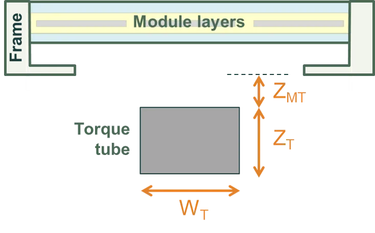
Dimensional parameters
Section titled “Dimensional parameters”- Diameter (DTT): For circular cross-sections
- Width (WTT): For rectangular cross-sections, horizontal dimension
- Height (HTT): For rectangular cross-sections, vertical dimension
- Inner diameter (DTT,inner): For hexagonal and octagonal cross-sections, diameter of inscribed circle
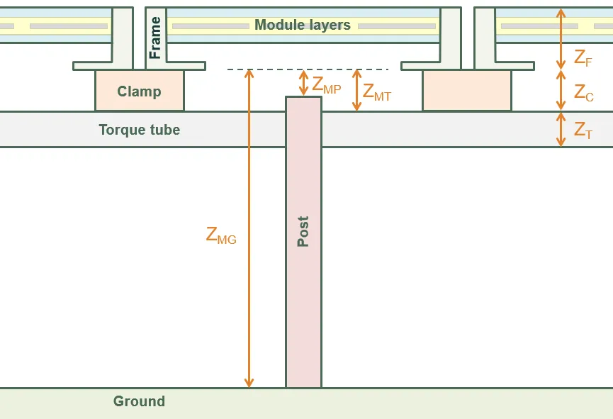
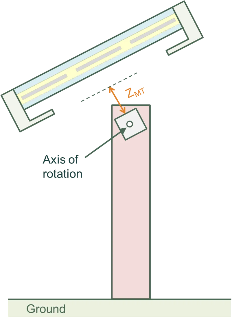
- Dist below module group (ZMT): Vertical distance from bottom of module group to top of torque tube
Posts are vertical support structures that transfer loads from the tracking system to the ground.
Cross section
Section titled “Cross section”The shape of the post in cross-section:
- Rectangular: Defined by X and Y dimensions
- Circular: Defined by diameter
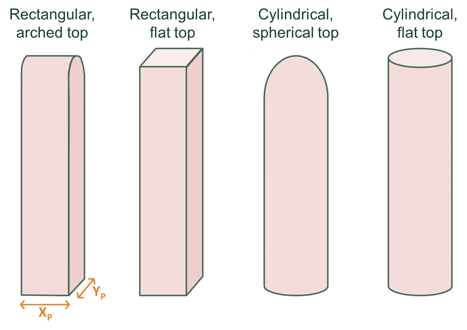
Top shape
Section titled “Top shape”The geometry of the post top (cap):
- Flat: Simple flat-top post with no cap (available for both circular and rectangular)
- Arch: Arched cap with half-cylinder shape (rectangular posts only)
- Hemispherical: Dome-shaped cap with half-sphere geometry (circular posts only)
The top shape affects the visual appearance and can impact ray tracing for light reflected off the post top. The figure below illustrates these options.
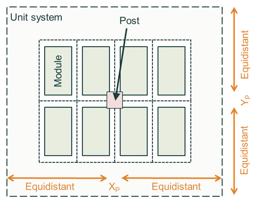
Post positioning
Section titled “Post positioning”Posts can be positioned in two layout modes:
Central
- Posts are distributed along the tracker axis beneath the torque tube
- Number of posts (Npost): Total number of posts per module group (1-10,000)
- Post-to-post pitch (Ppost): Horizontal center-to-center spacing between adjacent posts
- Posts are evenly distributed along the tracker length
Edge
- Posts positioned only at the unit system boundaries
- Two posts per tracker, located at the edges
- Posts are centered on the torque tube axis but located at the edge of the unit system
Edge handling for posts
Section titled “Edge handling for posts”When posts are positioned such that their width (cross-sectional dimension) would extend beyond the unit system boundary, they are automatically rendered as half-width elements positioned flush with the boundary. This ensures proper tiling when unit systems repeat infinitely.
- For circular posts: A half-cylinder is created instead of a full cylinder
- For rectangular posts: The width is halved
- The post is positioned so its flat edge aligns with the unit system boundary
Post height calculation
Section titled “Post height calculation”Post height is automatically calculated based on the distance from the top of the post to the bottom of the module frame (or module layers if no frame). The figure below illustrates this dimension.
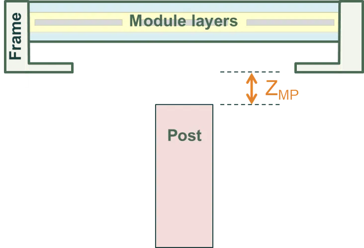
Dist from top of post to bottom of panel (ZMP): Vertical gap between the top of the post and the bottom of the module group.
Dimensional parameters
Section titled “Dimensional parameters”- X dimension (Xpost): For rectangular cross-sections, width in X direction
- Y dimension (Ypost): For rectangular cross-sections, width in Y direction
- Diameter (Dpost): For circular cross-sections
The options are shown in the figures below: (left) Central layout with posts distributed along the tracker, and (right) Edge layout with posts at the unit-system boundaries.
System height, tilt and axis of rotation
Section titled “System height, tilt and axis of rotation”Height definitions
Section titled “Height definitions”The figure below defines the vertical distances of the system components.
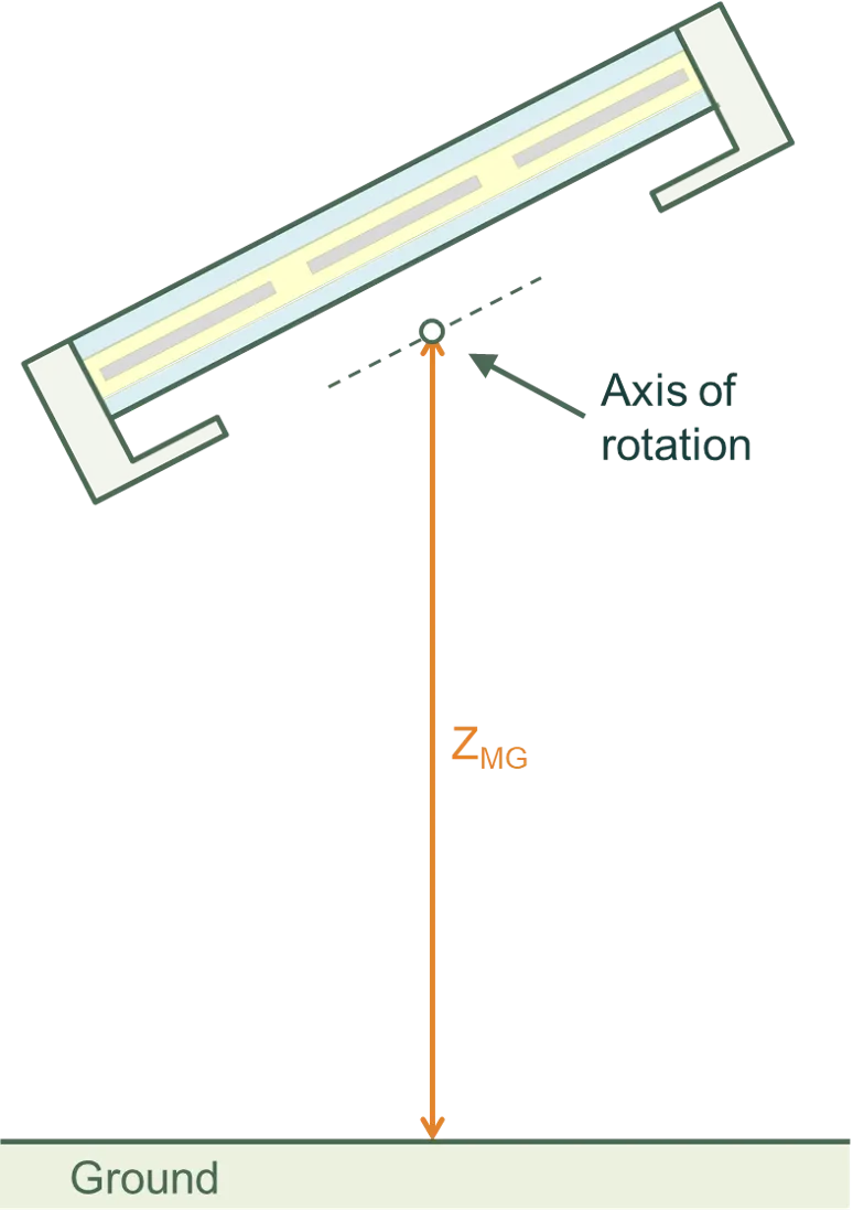
The most significant distance is ZMG, the height of the bottom of the module (including its frame) above the ground. The height above the ground of the clamps and torque tube, and the height of the posts, are all defined from ZMG.
All of these definitions are specific to a horizontal module; i.e., they assume the module tilt is zero.
Tilt orientation and direction
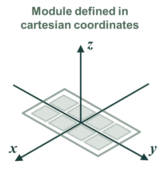
Section titled “Tilt orientation and direction”The modules of a system can be tilted in either X or Y directions. This allows you to tilt them in portrait or landscape, irrespective of how many cells are assigned to the X and Y directions.
The modules are then faced in any direction of the compass, as defined by the modules’ azimuth angle φ relative to due north.
For example, the figure below first shows how a module is defined in x/y coordinates. This module has two columns in the x direction and four rows in the y direction. The module is then tilted in the y direction by an angle β (where a positive β makes the front of the module face in the positive y direction). Finally, the module is assigned an orientation φM = 112.5° such that the front of the module faces east–south–east (for a positive β).
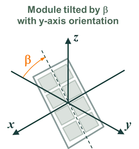
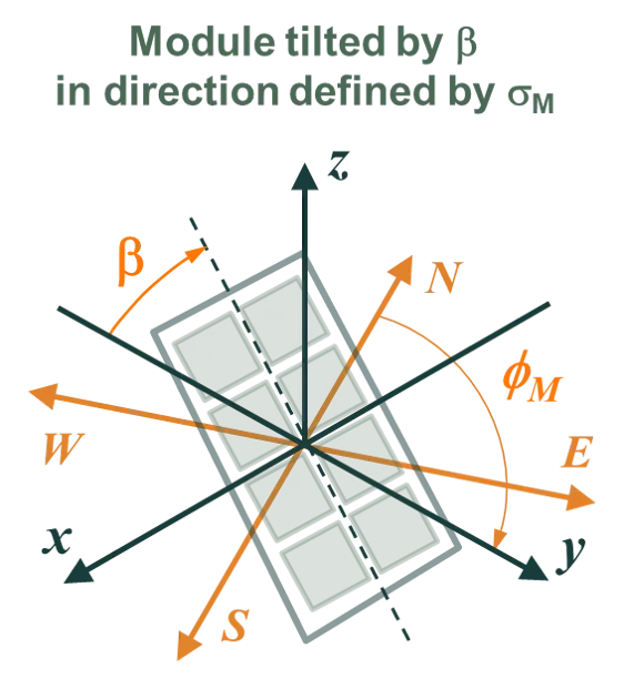
Note that in this example, a negative β would make the module face west–north–west.
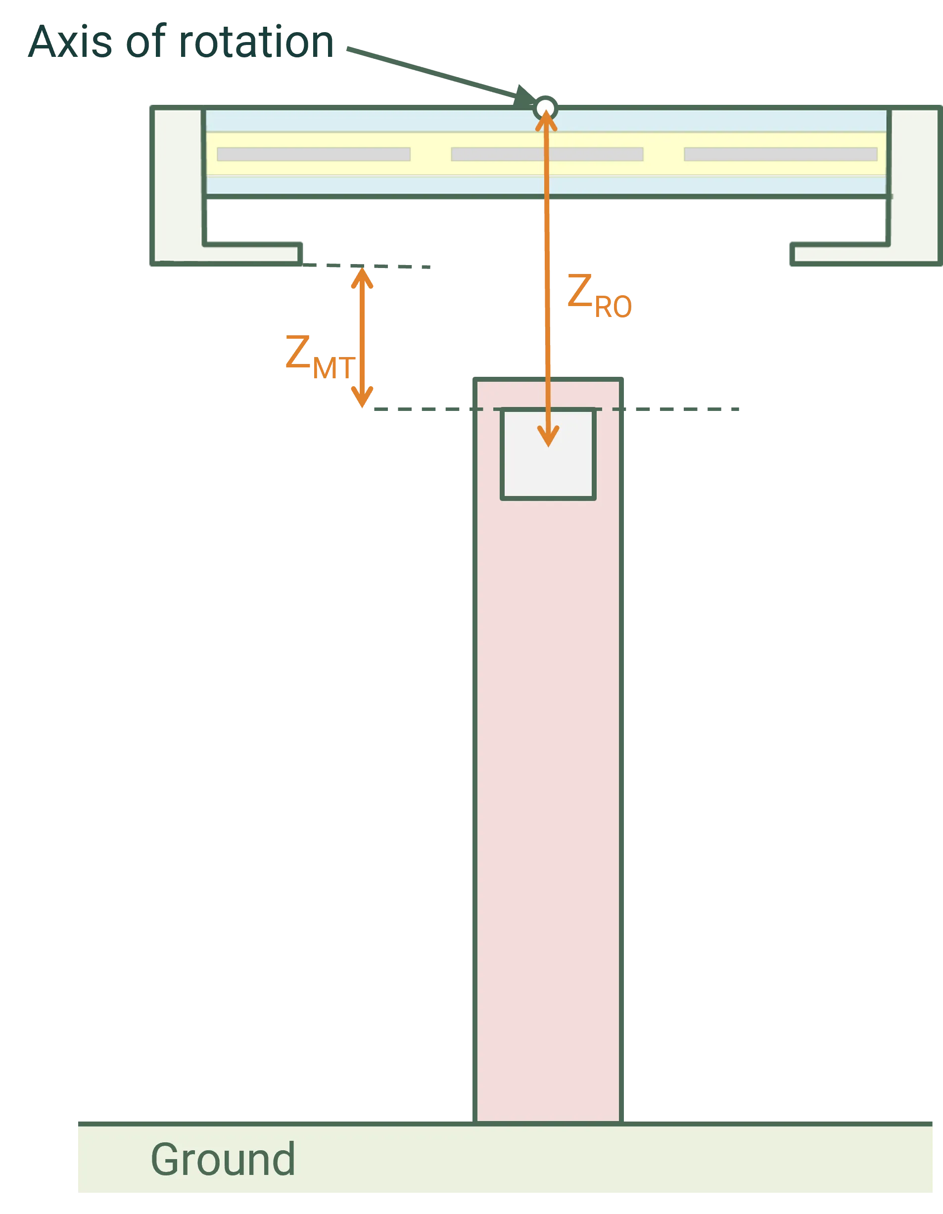
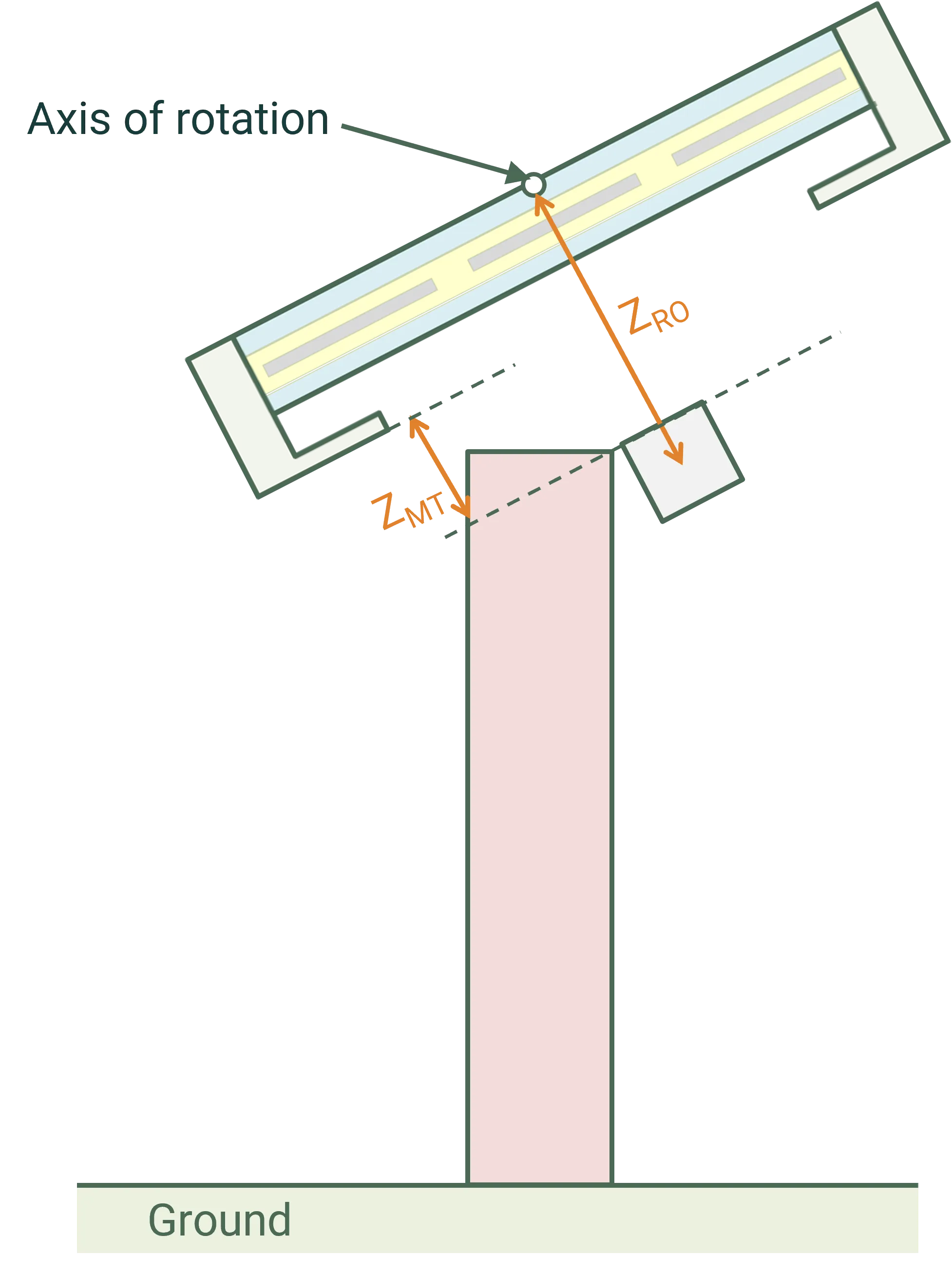
Axis of rotation for tilted modules
Section titled “Axis of rotation for tilted modules”The axis of rotation depends on whether a torque tube is included in the simulation.
With a torque tube, a non-zero tilt causes a rotation of the module, clamps, and torque tube about the axis of the torque tube.
Without a torque tube, a non-zero tilt causes a rotation of the module and clamps about the axis passing through the middle of the module in the XY plane and the bottom of the module in the Z plane.
In either case, the posts remain stationary.
The figures below indicate the axis of rotation with and without a torque tube.
Beginning with SunSolve version 6.15.0 it is also possible to define an additional rotation offset (ZRO). This offset shifts the location of the point around which the tilt rotation occurs as shown in the figure below. A positive offset increases the height of the rotation point above the ground (as shown in the figure), a negative offset causes it to be positioned closer to the ground. As described above this rotation is applied to the PV panels, clamps/rails and the torque tube. It is not applied to the posts.