Waves system layout
Wave systems feature modules arranged in pairs that face each other, creating a wave-like profile. These systems are typically used for flat-roof installations where modules are mounted on ballasted structures without penetrating the roof membrane.
System dimensions
Section titled “System dimensions”The unit-system dimensions for waves are determined using the module dimensions, module tilt and a series of gaps/separations which are defined below.
Module arrangement
Section titled “Module arrangement”- Lateral modules: Number of modules across the wave, orthogonal to the tilt direction (1-50 modules)
- Vertical modules: Number of modules stacked vertically in the wave, in the tilt direction (1-6 modules)
- Lateral module separation (LMS): Gap between adjacent modules across the wave (0-200 cm)
- Vertical module separation: Gap between vertically stacked modules when vertical modules > 1 (0-200 cm). This parameter is only shown when multiple vertical modules are configured.
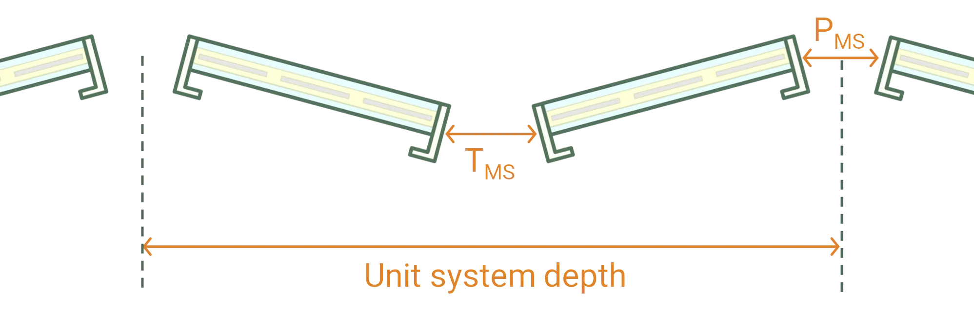
Peak and trough separations
Section titled “Peak and trough separations”A gap is defined at the peak (PMS) and trough (TMS) of the wave. This is measured from a point on the edge of the tilted module that is exactly half of the module thickness. The unit-system depth is then calculated as:
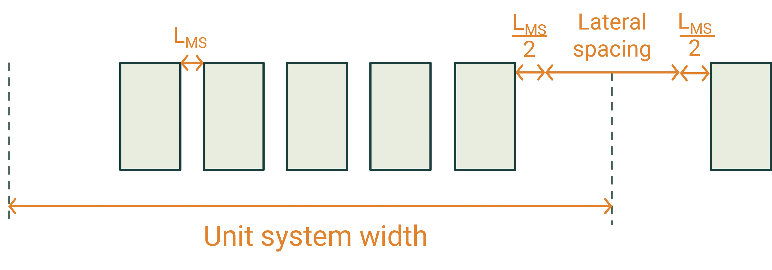
Lateral spacing
Section titled “Lateral spacing”The lateral module separation (LMS) between adjacent modules is applied across the wave. Half of that spacing is applied at each edge of the wave (see figure below).
An additional Lateral Spacing parameter defines extra spacing between waves in the infinite unit-system tiling. The unit-system width is then calculated as:
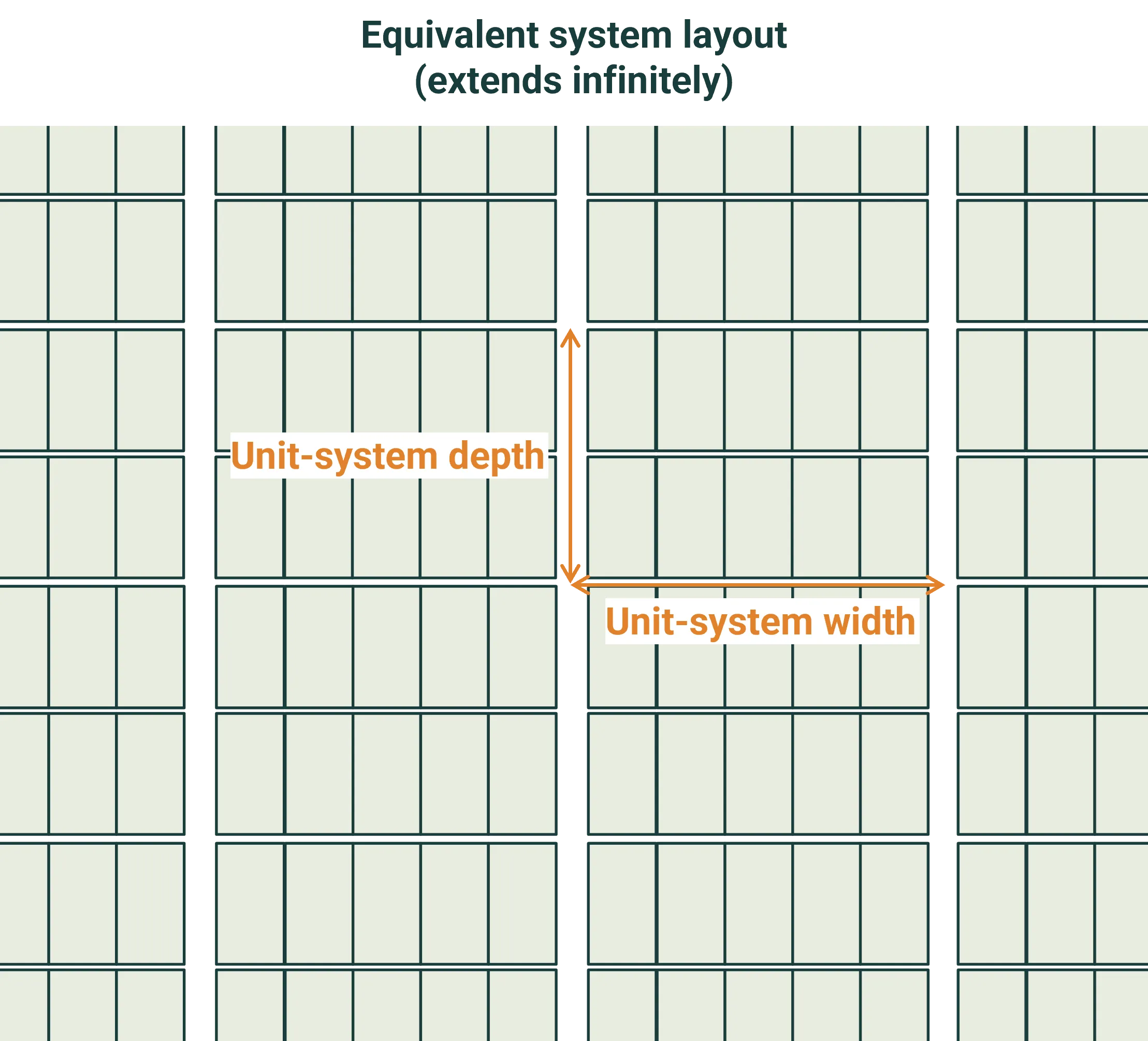
The wave unit-system is repeated infinitely in each direction. Thus the simulation represents a central wave within a large system and neglects any edge of system effects.
Ballasts
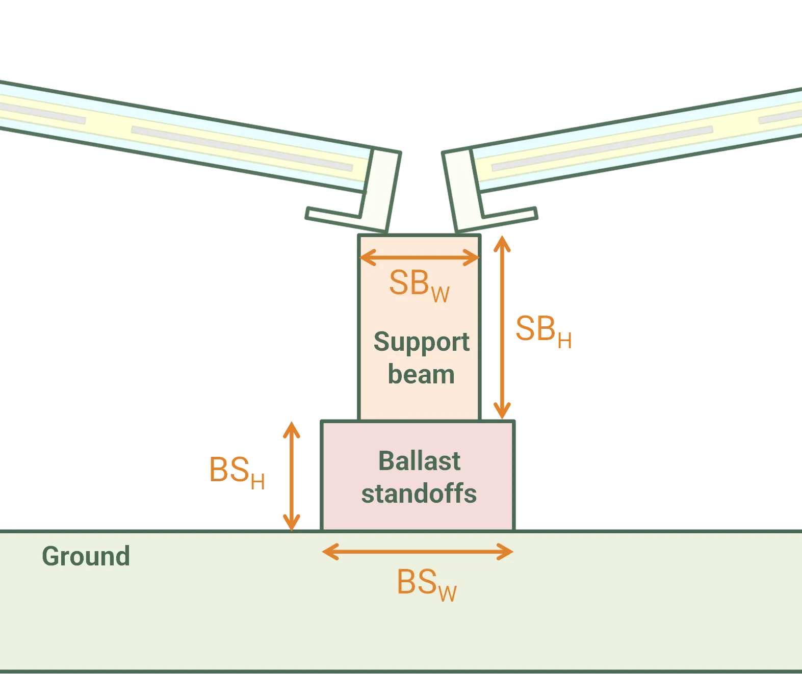
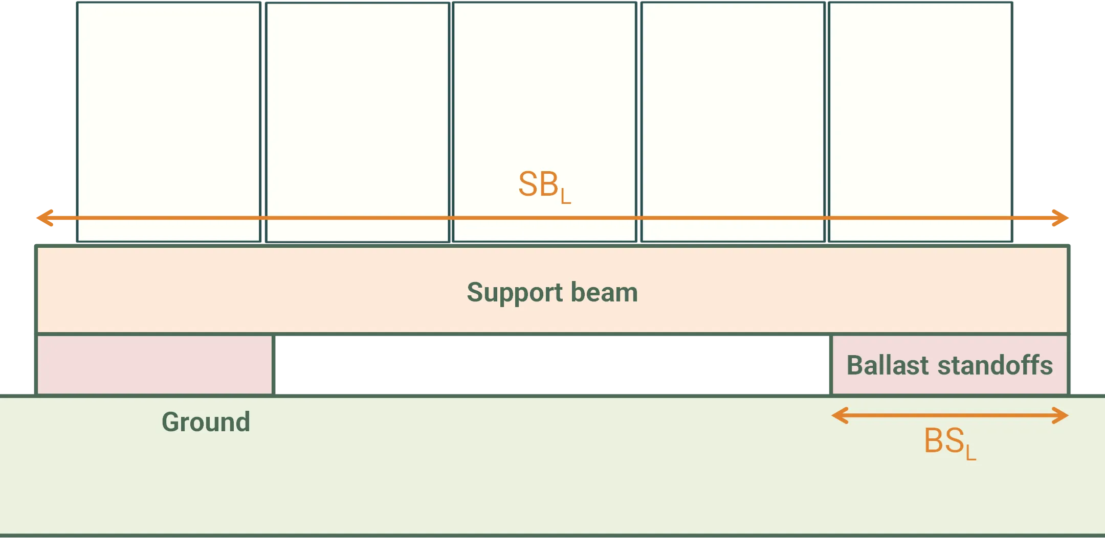
Section titled “Ballasts”Ballasts are positioned directly onto the ground and act to increase the vertical position of the modules. They are defined by support beams with optional standoffs and stabiliser wires. SunSolve treats the support beams and standoffs as rectangular prisms. The stabiliser wire is a cylinder.
Support beam dimensional parameters
Section titled “Support beam dimensional parameters”- Width (SBW): Horizontal dimension perpendicular to beam length (0-10,000 cm)
- Height (SBH): Vertical dimension of support beam (0-10,000 cm)
- Length (SBL): Length of support beam along wave direction (0-10,000 cm)
Standoff dimensional parameters
Section titled “Standoff dimensional parameters”- Width (BSW): Horizontal dimension perpendicular to standoff length (0-10,000 cm)
- Height (BSH): Vertical dimension of standoff (0-10,000 cm)
- Length (BSL): Length of standoff (0-10,000 cm)
- Number of standoffs: Count per support beam
- Pitch (BSP): Spacing between standoffs (for Fixed pitch mode, 0-10,000 cm)
Stabiliser wire parameters
Section titled “Stabiliser wire parameters”- Diameter (SWD): Diameter of cylindrical stabiliser wire (0-10,000 cm)
- Offset from edge (SWO): Distance from edge of support beam (0-10,000 cm)
The figures below define these dimensions.
Standoff spacing options
Section titled “Standoff spacing options”There are two options for setting the pitch of the standoffs. In both cases the spacing is centered on the middle of the support beam.
-
Evenly spaced: pitch is set such that the edge of the first and last standoffs aligns with the edge of the support beam and remaining standoffs are uniformly spaced.
-
Fixed pitch: pitch is entered by user via the BSp input. This setting should be used if the standoffs are positioned back from the edge of the support beam.
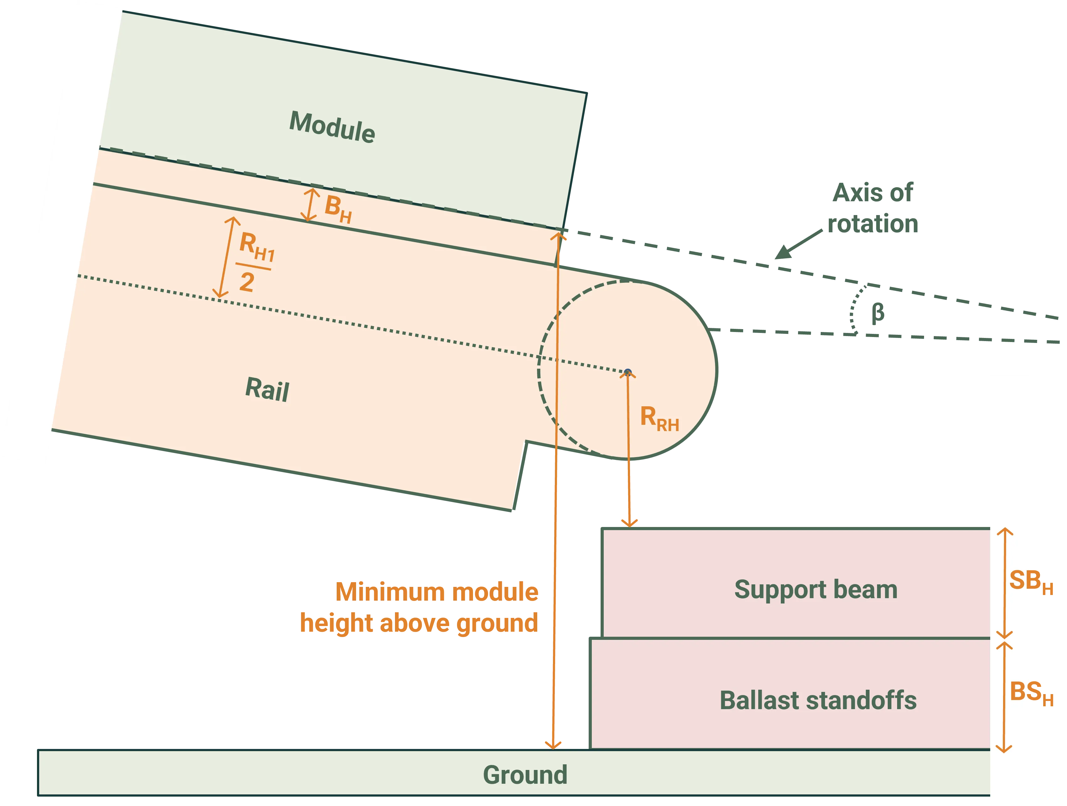
The rails support the modules and adjust the module vertical position. There are rails located at the corners of every module (i.e., in the wave trough and peak). The vertical position of the lower set of rails is defined either relative to the top of the ballast support beam, or relative to the ground when there is no support beam. The rotation height RRH is the distance between that reference point and the point of rotation (see Height definitions section for more details). The upper rails are aligned to the top of the modules.
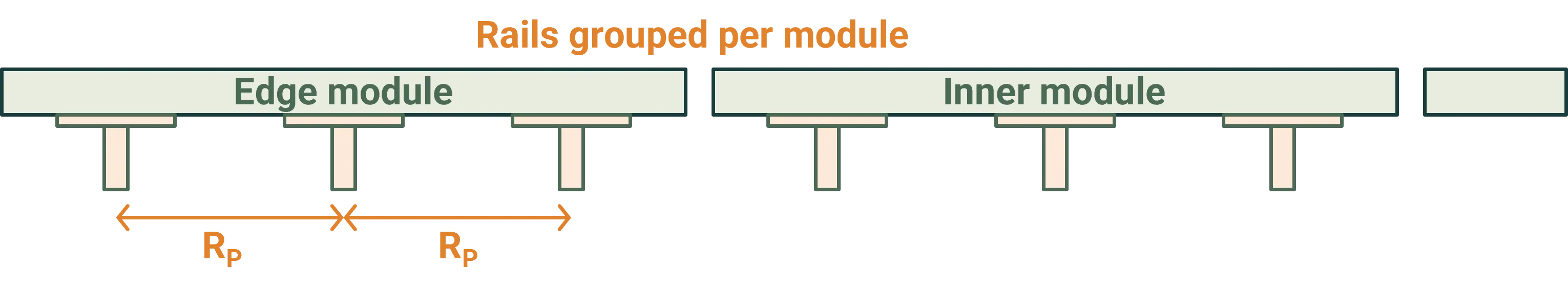
Rail arrangement options
Section titled “Rail arrangement options”The location of the rails laterally across the wave is controlled by the Arrangement setting:
Aligned to module edges (standard)
- Center of rail is aligned to the center of the lateral gap between modules
- Bottom of module is aligned to the top of the bracket
- One rail at each gap, and a rail with a single bracket (facing inwards) at the edges of the wave

Grouped per module (requires advanced waves permissions)
- Multiple rails distributed per module with configurable spacing
- Number of rails: Count of rails per module group
- Rail pitch (RP): Center-to-center spacing between rails within a group (0-10,000 cm)
- Rails are centered on each module with pitch spacing between them
- Rail shape is rotated 180 degrees (inverted) compared to the edge-aligned option
- Lowest point of the module sits directly on the bracket
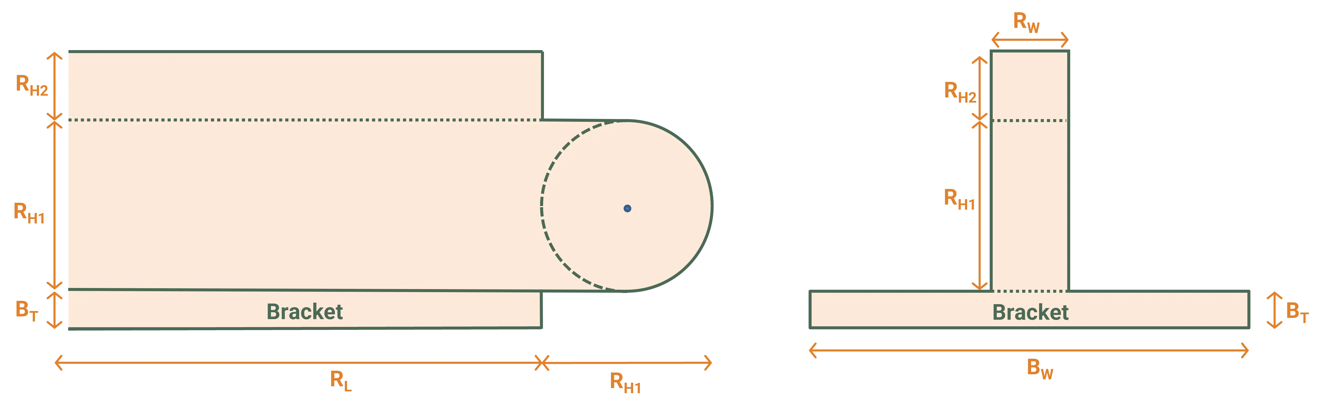
Rail dimensional parameters
Section titled “Rail dimensional parameters”The rail shape is comprised of a bracket (to support the module) and two sections of rails:
- Rail length (RL): Length of rail along the module edge (0-10,000 cm)
- Rail inner width (RW): Width of the rail channel (0-10,000 cm)
- Rail height (main) (RH1): Height of the first (main) rail section including circular joint (0-10,000 cm)
- Rail extra height (RH2): Additional rail height above the main section (0-10,000 cm)
- Bracket width (BW): Width of the module support bracket (0-10,000 cm)
- Bracket height (BH): Vertical height of the bracket (0-10,000 cm)
- Rotation height (RRH): Vertical distance from reference point (top of support beam or ground) to the rotation point (0-10,000 cm)
The first rail section RH1 includes a circular joint, the center of which defines the height of the rail and module (see Height definitions section). The diameter of the rounded section is set by RH1 and adds additional length to the rail.
Joints
Section titled “Joints”Joints provide a rectangular block located across the rotational points of the rails. They are applied laterally across the wave, at the top and bottom of the modules, at any location where there are rails. At the top of the modules the joints are aligned vertically to the top of the unit-system box. At the bottom of the module the joints are positioned either directly on the top of the support beam, or directly on the ground (if no support beam is used). The joints do not impact the height of the modules or their axis of rotation.
Joint dimensional parameters
Section titled “Joint dimensional parameters”The dimensions of the joints are defined separately for upper and lower locations:
Lower joints:
- Width (JW,lower): Horizontal dimension perpendicular to wave direction (0-200 cm)
- Height (JH,lower): Vertical dimension (0-200 cm)
- Breadth (JB,lower): Dimension along wave direction (0-200 cm)
Upper joints:
- Width (JW,upper): Horizontal dimension perpendicular to wave direction (0-200 cm)
- Height (JH,upper): Vertical dimension (0-200 cm)
- Breadth (JB,upper): Dimension along wave direction (0-200 cm)
System height, tilt and axis of rotation
Section titled “System height, tilt and axis of rotation”Height definitions
Section titled “Height definitions”The figures below define the vertical distances of the system components critical to the determination of the module height.
The module height from the ground is increased by the ballast support beam (SBH), ballast standoffs (BSH) and the rail rotation height (RRH). The module height is then either increased or decreased by the rail arrangement and dimensions.
Arrangement aligned to module edges: the module height includes adjustments for the rail geometry and module tilt.
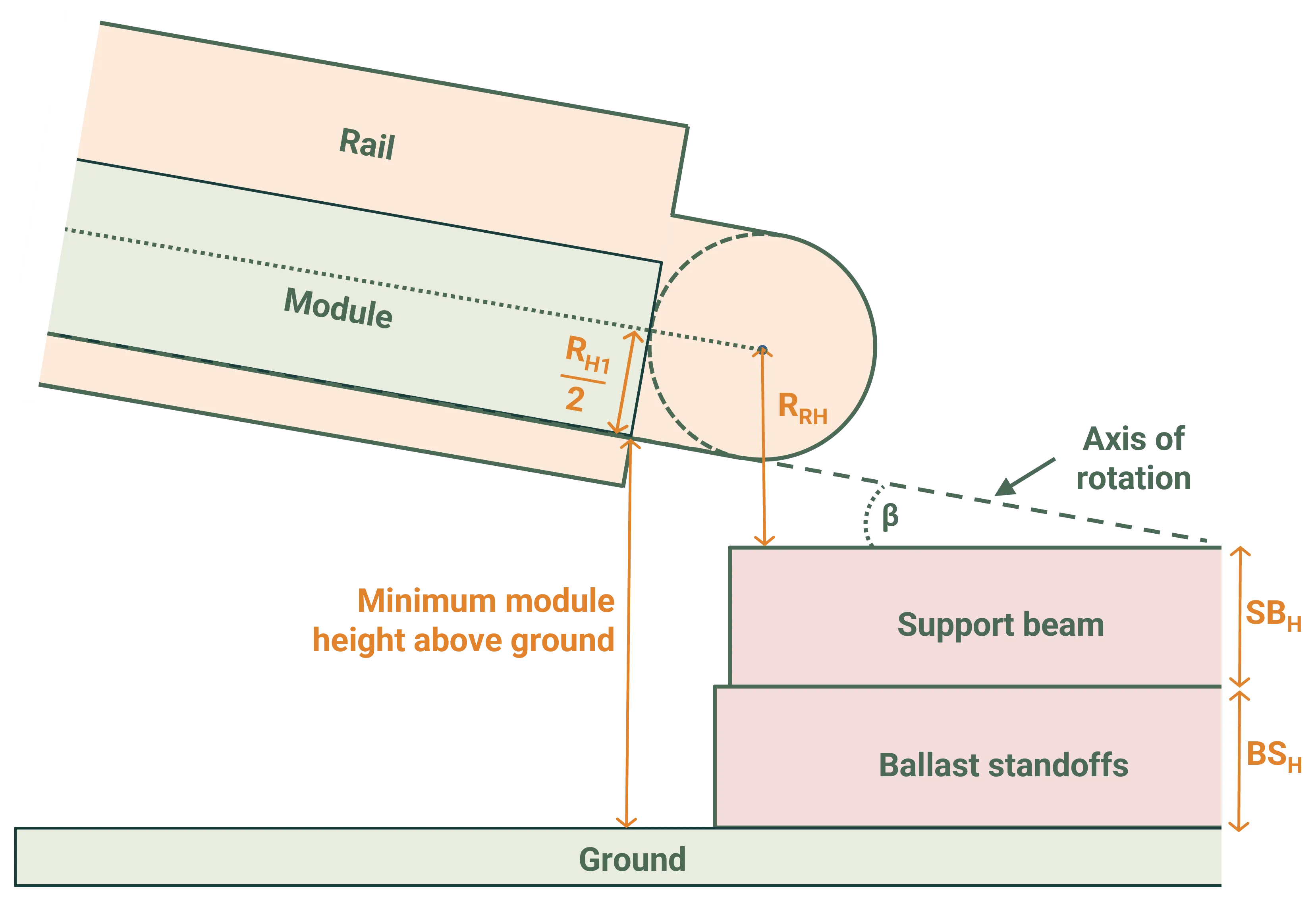
Where the final term accounts for the vertical contribution from the tilted module.
Arrangement grouped per module: the module height includes additional bracket height and full rail height terms.
Where the final term accounts for the vertical contribution from the tilted module.
Tilt orientation and direction
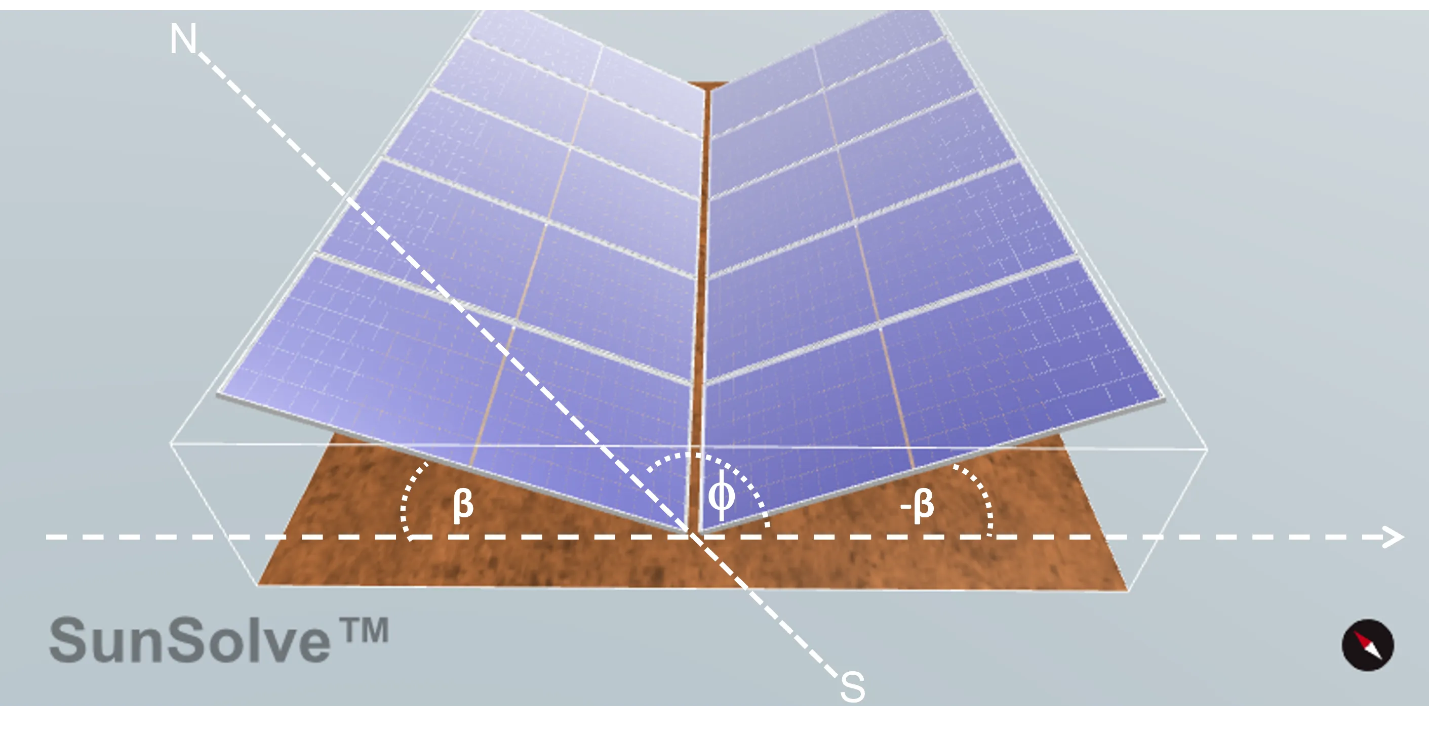
Section titled “Tilt orientation and direction”Waves are defined by two tilt orientations; a primary tilt and a secondary tilt. The primary panels are tilted by an angle (β) in the direction defined by the azimuth angle (φ) relative to due north. The secondary panels are tilted by -β which effectively gives them an orientation that is 180 degrees opposite the primary panels. In the time series output files this will appear as a negative tilt. Note that it is possible to reverse the wave direction by entering a negative tilt, however in this case the system components may not be correctly aligned.
Axis of rotation
Section titled “Axis of rotation”The axis of rotation is always aligned to the bottom edge of the module.