
Custom objects
Custom objects provide the most flexible way to define structure within the 3D scene. They can be used to add details to a scene that is primarily defined with standard structure or they can provide the entire definition of the system structure.
A custom mesh is a 3D shape definition stored in the mesh library — either a built-in primitive or a shape imported from an STL file. A custom object is a scene instance of a custom mesh: it references a mesh from the library and adds placement properties (position, size, rotation, layout, and material). Multiple custom objects can reference the same mesh, allowing the same shape to appear in different positions, sizes, or with different materials within a single scene. Like all objects in the unit system, custom objects repeat infinitely across the infinite array.
Custom objects are configured on the Structure sub-tab of the System tab, alongside the standard structure. Use + Add custom object to add one and × Remove all custom objects to clear them.
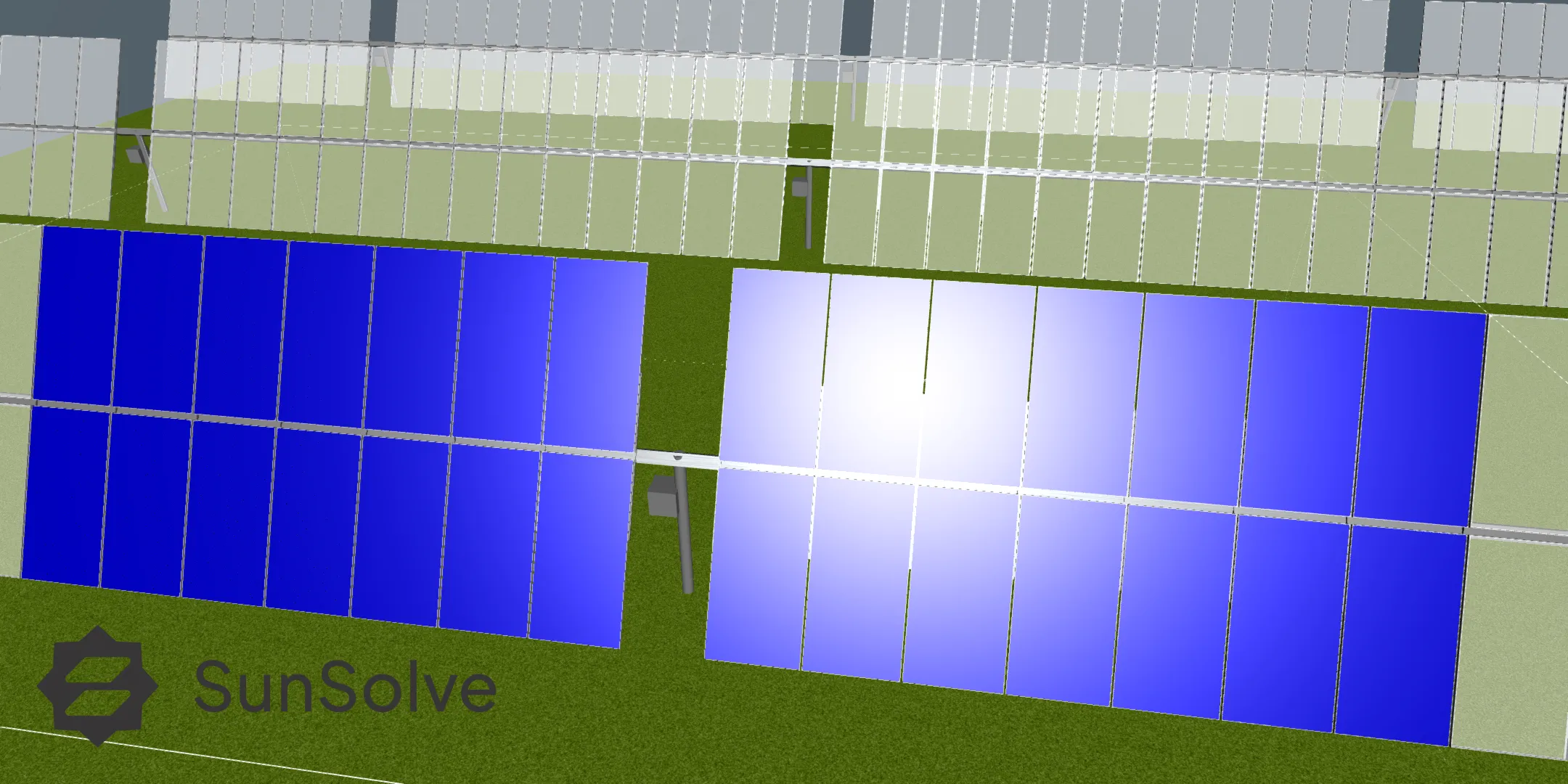
Built-in meshes
Section link: Built-in meshesThe following primitive meshes are available by default under the “Basic” folder:
- Box
- Sphere
- Cylinder
- Semi-Sphere
- Semi-Cylinder
Additional meshes can be imported from STL files; see Importing custom meshes from STL.
Object properties
Section link: Object propertiesEach custom object has the following configurable properties:
Location, Determines the parent reference frame: System - Fixed (stationary),, System - Tracking (rotates with a single-axis tracker),, or Module (relative to each module).
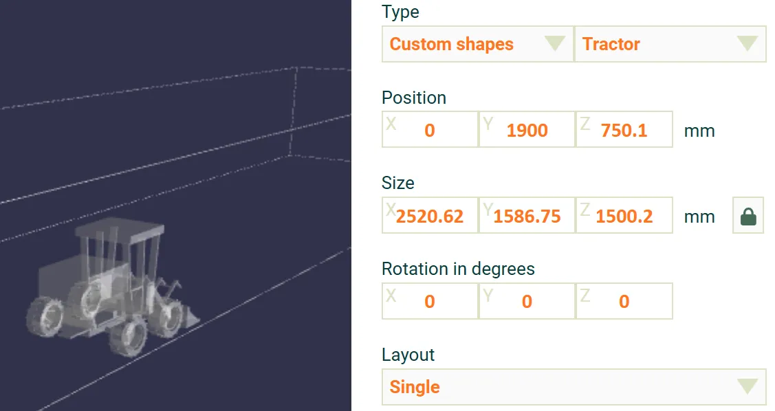
Size, Scale of the object along each axis. A lock toggle constrains all three axes to scale uniformly.
Layout, Single places one object. Repeated repeats the object with configurable spacing and count.
Transparent, When enabled the object is excluded from ray tracing and appears in the system image only.
Full-surface absorber, When enabled the object reports its absorbed energy density on the Sensors tab. Not available when the object is transparent or uses a repeated layout.
Material, The optical surface applied to the object. See Optical surfaces for the material presets,, custom reflectors and scattering options.
Repeated layout
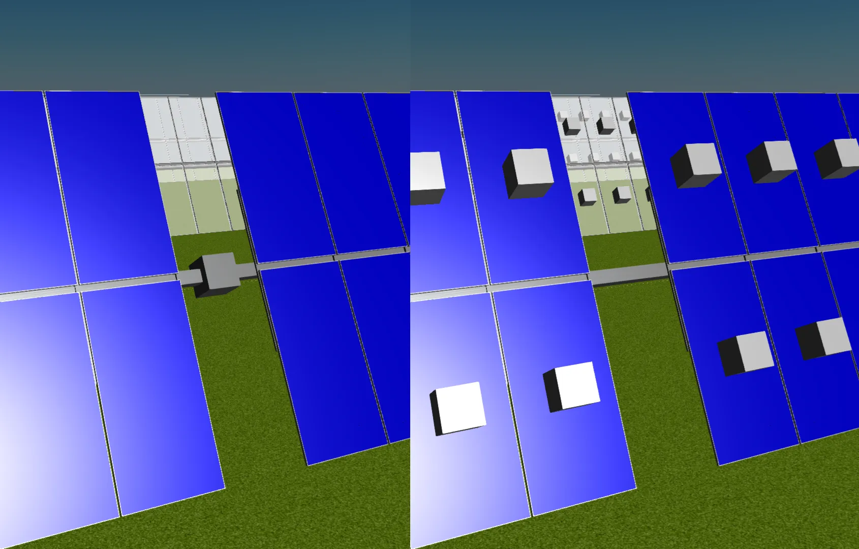
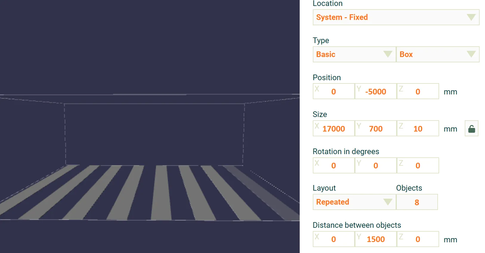
Section link: Repeated layoutWhen the layout is set to Repeated, the object is repeated a specified number of times with a configurable spacing in X, Y, and Z.
Full-surface absorber
Section link: Full-surface absorberEnabling Full-surface absorber turns a custom object into a sensor that measures the energy it absorbs. Unlike a dedicated sensor, which can report irradiance on defined front and rear facets, a full-surface absorber records absorption across every face of the object.
The absorbed energy is derived from the object’s assigned material. Custom objects never transmit light: every ray that reaches the surface is either reflected or absorbed, so the reflectance and absorptance always sum to one. At each timestep the sensor records the absorbed fraction . Because a fraction of the incident light is reflected, the result is an absorbed energy density rather than the incident irradiance. It is reported on the Sensors output tab, labelled Custom Object N to match the object’s position in the list.
The Full-surface absorber checkbox is disabled when the object is transparent (a transparent object is excluded from ray tracing) or uses a repeated layout (a full-surface absorber must be a single object).
The assigned material must be a reflector surface, either constant or wavelength-dependent. A Fresnel surface is not supported for a full-surface absorber; the simulation reports an error until you select a reflector surface or disable the option.
Importing custom meshes from STL
Section link: Importing custom meshes from STLCustom meshes can be imported from .stl files via the Custom meshes tab in the right panel.
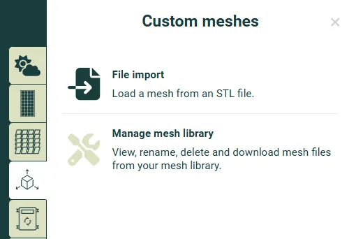
In the Custom meshes tab, select File import (Load a mesh from an STL file), then Select STL file. After loading, the default scaling and rotation can be adjusted before clicking Next. Finally, choose a folder and a name, then click Import. The imported mesh will then appear under Type > Custom meshes when configuring a custom object.
The maximum STL file size is 25 MB. Only the STL format is supported; other 3D formats such as DWF or DXF must be converted to STL before importing.
Mesh simplification
Section link: Mesh simplificationAfter selecting a file, a 3D preview is shown. If the mesh has more than 10,000 triangles, a simplification slider appears on the preview tab so you can reduce the triangle count and see the result before importing. For best performance, aim for fewer than 10,000 triangles (approximately 1 MB when saved). Meshes exceeding 50,000 triangles cannot be imported until simplified below this limit.
See Exporting low-polygon STL files for a step-by-step guide to producing compact STL files from SolidWorks or Onshape.
3D preview
Section link: 3D previewEach custom object includes an interactive 3D preview showing the object within its parent reference frame.
- Toggle origin axes displays the X, Y, and Z coordinate axes of the parent reference frame (system fixed node, tracking node, or module) in the preview, helping to verify position and orientation.
Validation
Section link: ValidationObjects positioned outside the unit system bounds or more than 10 m above the system are excluded from the simulation. When this occurs, the unit system boundary box turns red and a warning is displayed in the preview.