
System layout
The Layout tab defines the system type and the arrangement, orientation and height of the modules within a repeating unit system.
This documentation page assumes the Landscape/portrait definition of system dimensions. With this definition, dimensions are expressed relative to the rows and the module orientation. The advanced XY axes (as used to define module) definition expresses the same layout using the X and Y axes of the module and is not covered on this page.
System type
Section link: System typeSystem type determines how the modules are arranged and which Layout and Standard structure inputs are available. There are three options:
- Fixed holds the modules at a fixed tilt angle and azimuth.
- Single axis tracker allows the modules to rotate about an axis to follow the sun.
- Waves arranges opposing tilted modules into a repeating wave pattern. This configuration is sometimes referred to as domes.
Changing the system type converts the existing system into the new type. However, for a new simulation, it is recommended to start from a template on the opening page of SunSolve for the required system type. This will ensure that the related inputs receive suitable initial default values.
Module layout
Section link: Module layoutModule layout defines the number of modules in a module group and the gaps between them. A module group is the set of modules represented within one unit system.
For Fixed and Single-axis tracker systems, the common inputs are:
- Lateral modules, the number of modules along the row axis.
- Vertical modules, the number of modules in the direction perpendicular to the row axis.
- Lateral separation, the gap between adjacent modules along the row axis.
- Vertical separation, the gap between adjacent modules perpendicular to the row axis.
Single-axis tracker bays
Section link: Single-axis tracker baysFor a Single-axis tracker, there is an additional option that determines whether the row contains one continuous bay or multiple bays:
- Single bay places all lateral modules in one continuous group. Lateral separation is applied between each module.
- Multiple bays divides the row into separate groups of modules and displays the Bay configuration section.
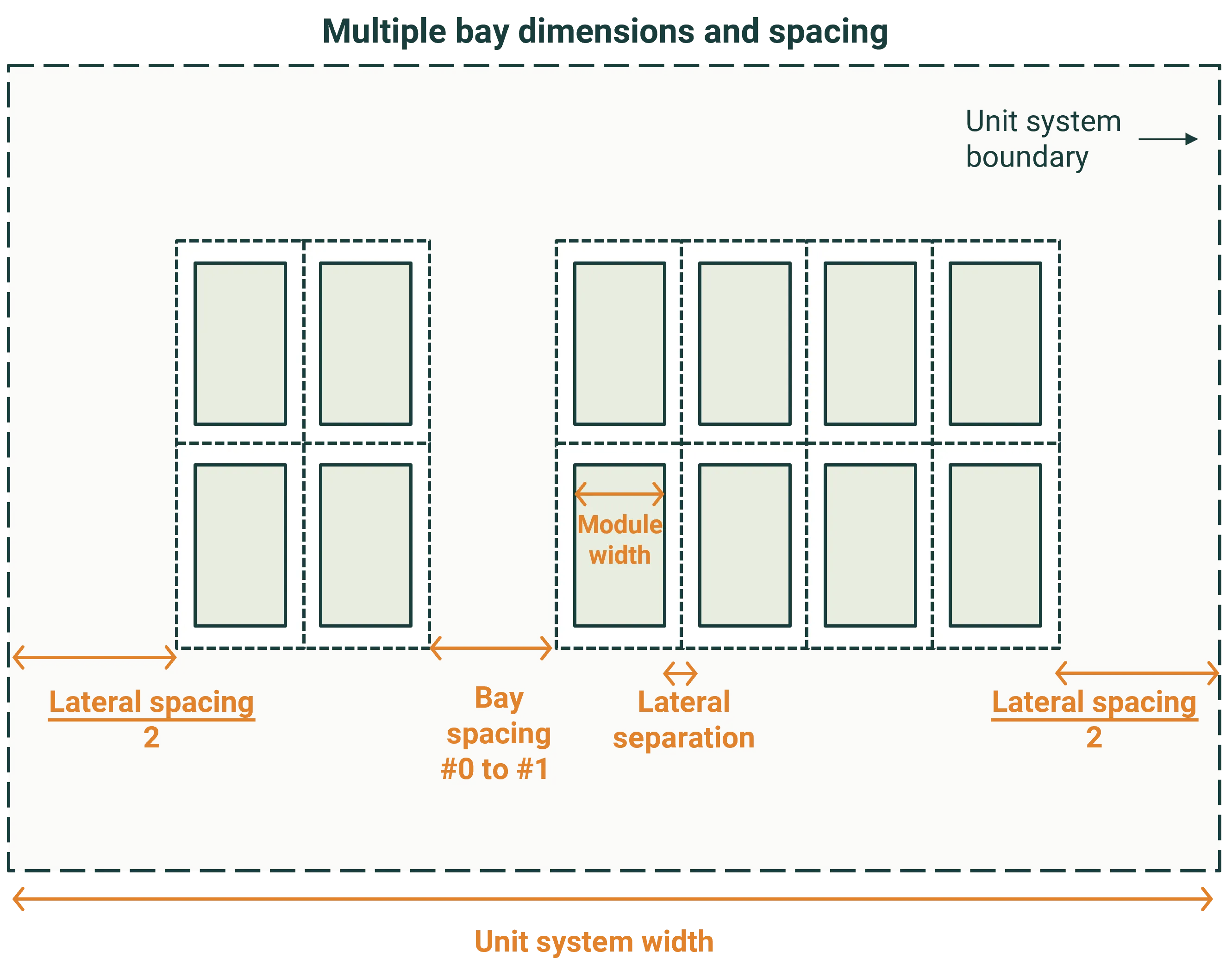
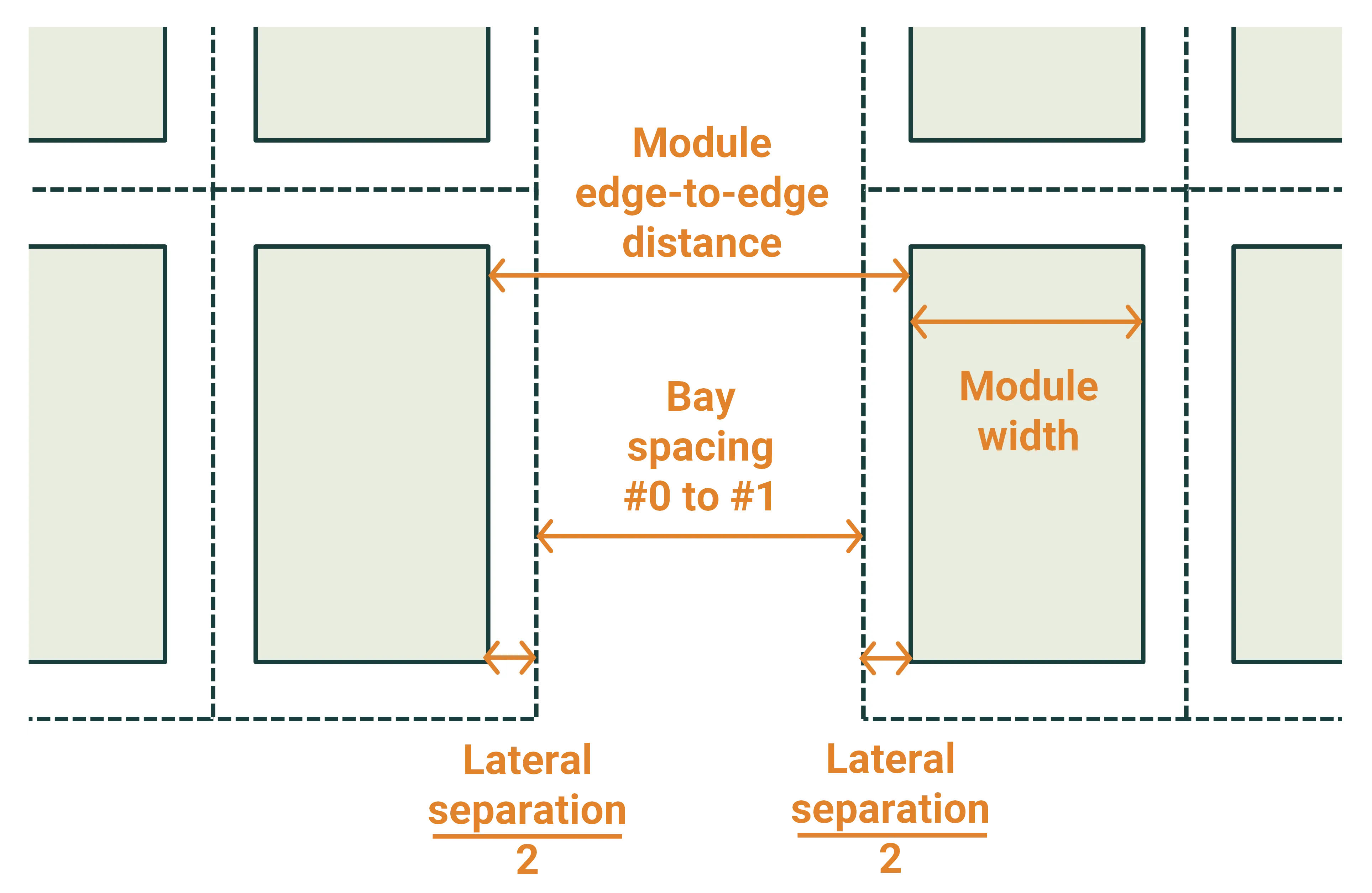
Bay configuration defines Number of bays, the Number of modules in each bay and the Bay spacing between adjacent bays. Each bay can contain a different number of modules. Bay spacing affects the optical model but is not used by the simplified thermal model.
Waves module layout
Section link: Waves module layoutFor Waves, Lateral modules sets the number of modules across the wave, perpendicular to the tilt direction. Vertical modules sets the number of modules on each tilted face.
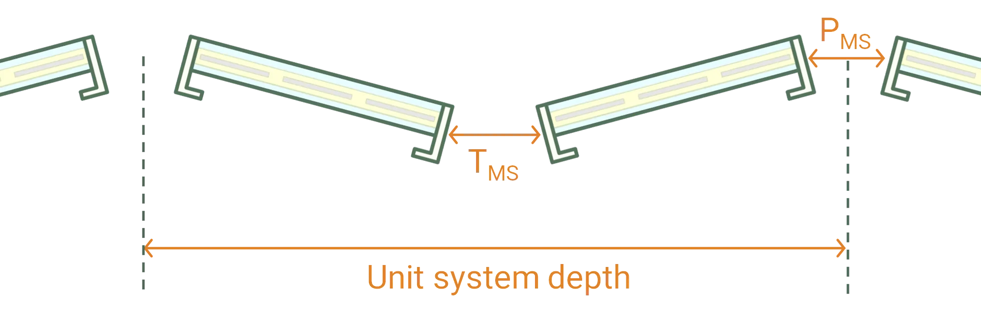
Gap at edge defines the separation at the peak of the wave, and Gap in center defines the separation at the trough. Each gap is measured between points halfway through the module thickness.
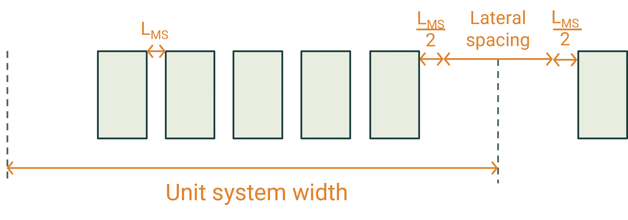
Lateral sep defines the gap between adjacent modules across the wave. Half of this separation is placed at each lateral edge of the module group. Vertical sep defines the gap between modules on the same tilted face and is shown when more than one vertical module is configured.
Unit-system dimensions
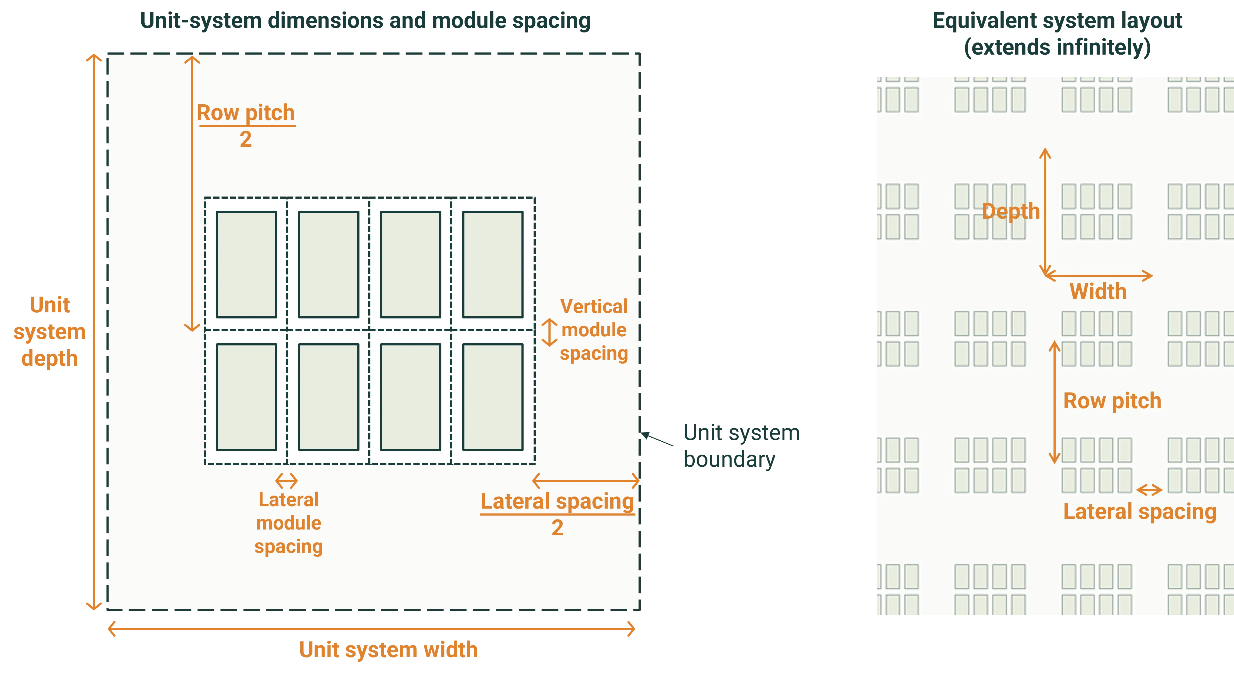
Section link: Unit-system dimensionsA unit system is a representative section of the array that repeats infinitely in both horizontal directions. It contains the module group, the space around it and the associated mounting structure. This repetition represents modules in the interior of a large installation without modelling the array edges.
For Fixed and Single-axis tracker systems, Row pitch is the distance between corresponding points in adjacent rows, measured in the tilt direction. Lateral spacing is the clear distance between adjacent module groups along the row axis.
Waves unit-system dimensions
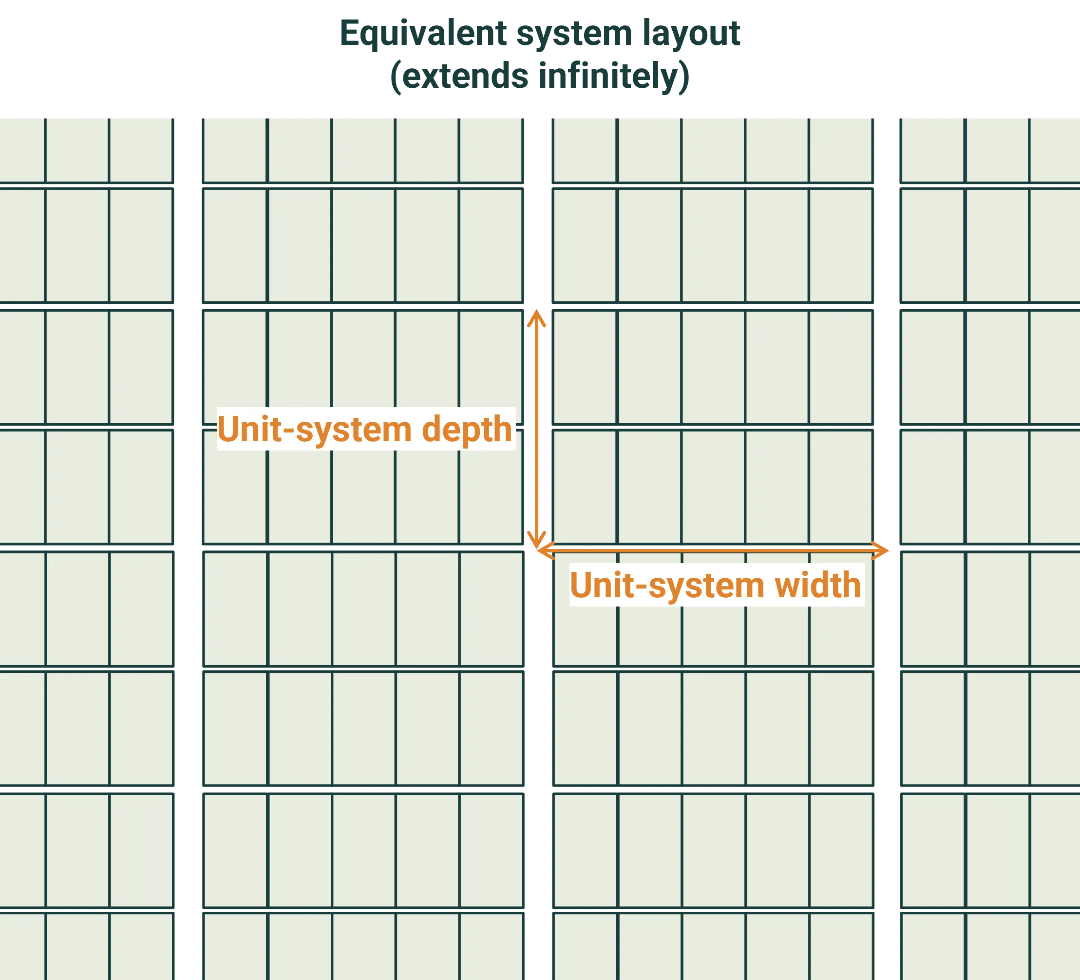
Section link: Waves unit-system dimensionsFor Waves, Row pitch is not shown. The unit-system depth is calculated from the module dimensions, tilt angle, Gap at edge and Gap in center. Lateral spacing adds clear space between adjacent waves along the lateral axis.
The resulting unit system repeats in both horizontal directions, as shown below.
Orientation
Section link: OrientationOrientation defines how the modules face and tilt relative to the ground and compass directions.
For all system types, Module orientation specifies whether the modules are in portrait or landscape orientation relative to the row. Tilt azimuth defines the compass direction faced by the front of a module with a positive tilt. 0° is north, 90° is east, 180° is south, 270° is west. For a system that tracks from east to west, use 90°.
For Fixed systems, Tilt angle defines the fixed module tilt. A negative tilt reverses the facing direction relative to Tilt azimuth.
Single-axis tracking orientation
Section link: Single-axis tracking orientationThere are two options for the Tracking algorithm to use:
- None disables tracking and holds the panels at a constant tilt. This is equivalent to a fixed tilt system, albeit with the tracking structure. It is used to simulate tracking systems that have been parked at a specific angle.
- Single axis enables the tracking algorithm described in module orientation and tilt.
With tracking set to None, the following inputs are shown:
- Tilt angle defines the fixed module tilt as it does for a Fixed system.
With Single axis tracking, the following inputs are shown:
- Tilt limit, min and Tilt limit, max constrain the range through which the modules can rotate. The sign of each value matters; typically, the minimum tilt value is negative.
- Night stow defines the module tilt when the sun is below the horizon. This may impact the module temperature at night if the extended Faiman model is used.
- Backtracking selects the tilt algorithm to use when the sun is low in the sky. The associated P on L ratio is the ratio of row pitch to tip-to-tip module length used by the backtracking calculation.
For a detailed description of the tracking algorithms, including the backtracking and tilt limits, see module orientation and tilt.
Waves orientation
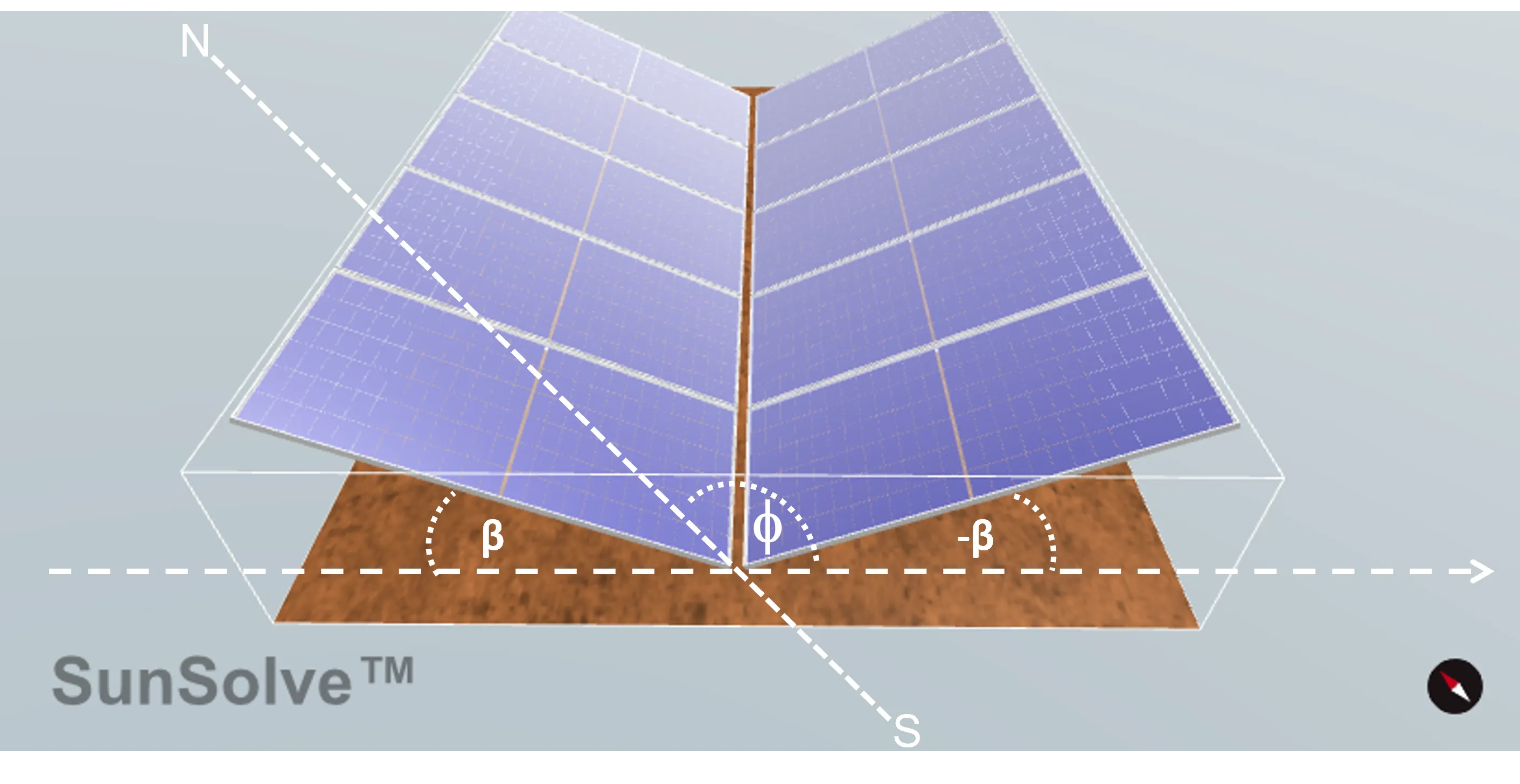
Section link: Waves orientationFor Waves, Tilt angle tilts the primary modules in the direction defined by Tilt azimuth. The secondary modules are tilted by and therefore face in the opposite direction.
Module height above ground
Section link: Module height above groundModule height defines the vertical position of the modules and reports their minimum and maximum clearance as they tilt. This section of the documentation applies to Fixed and Single-axis tracker systems. For Waves, module height is calculated from the ballast and rail geometry described under Waves system height.
At 0° tilt is the height of the bottom of the module group above ground when the modules are horizontal. The supporting structure is positioned relative to this module height.
Minimum at ° and Maximum at ° report the lowest and highest points of the module group at the relevant tilt. For a Fixed system, this is the configured tilt angle. For a tracker, it is the larger absolute value of the minimum and maximum tilt limits.
Use → Set minimum module height to enter the required minimum clearance instead. SunSolve then calculates the corresponding At 0° tilt height.
Axis of rotation
Section link: Axis of rotationThe axis of rotation is the line about which the modules and any rotating structural components tilt. Height above ground reports the calculated height of this axis.
For a Fixed system, the axis position depends on the enabled purlins and rafters. For a Single-axis tracker, it depends on the torque-tube geometry when a torque tube is enabled. See Fixed axis of rotation and Tracker axis of rotation for these relationships.
For a Single-axis tracker, Vertical offset moves the rotation axis vertically from its calculated position. A positive offset raises the axis and a negative offset lowers it. The modules, clamps and torque tube rotate about the resulting axis, while the posts remain stationary.
SunSolve uses the physical geometry of the module and structure to locate the axis rather than assuming that the modules have no thickness or always rotate about their geometric centre.
Dimensions
Section link: DimensionsDimensions reports the calculated size and area of the module group and unit system. These outputs update when the module arrangement, orientation, spacing or structural geometry changes.
Total module area
Section link: Total module areaTotal module area is the area of one module multiplied by the number of modules in the unit system:
Unit-system area
Section link: Unit-system areaUnit-system area is the horizontal area enclosed by the unit-system width and depth :
Tip to tip length
Section link: Tip to tip lengthTip to tip length is the full module-group extent in the tilt direction when the modules are horizontal. It includes the modules and the separations between them.
The ground coverage ratio GCR is the tip-to-tip length divided by the row pitch :
This is a two-dimensional ground coverage ratio in the row-to-row direction.
Module group dimensions
Section link: Module group dimensionsModule group width is the total extent of the modules and their separations along the row axis. Module group length is the corresponding extent perpendicular to the row axis. These outputs are not shown for a multiple-bay tracker because its bays can contain different numbers of modules.
Calculated unit-system dimensions
Section link: Calculated unit-system dimensionsUnit system width and Unit system depth are the horizontal extents of one repeating unit system. They include the module-group dimensions and the spacing to adjacent unit systems. For a tilted system, these are plan dimensions and do not change with the instantaneous module tilt.