
Standard structure
The standard structure is the mounting hardware that supports the modules, such as posts, rafters, purlins, torque tubes, clamps, ballast blocks, rails and joints. It is configured on the Structure sub-tab of the System tab, alongside custom objects.
The structural components available depend on the System type chosen on the Layout sub-tab. Each enabled component is ray traced, so it can shade the modules and reflect light onto them.
Enabling components
Section link: Enabling componentsEach structural component has a checkbox that enables or disables it. Only the components relevant to the selected system type are shown:
For Waves systems, standoffs and stabiliser wires are available only when the ballast block is enabled, and joints are available only when rails are enabled.
Optical material
Section link: Optical materialEach structural component is assigned an optical material that determines how its surface reflects and absorbs light during ray tracing. Select a material from the component’s dropdown, which lists common structural materials such as galvanised steel, oxidised galvanised steel, concrete, and anodised aluminium alloy.
Click → Show details to see how the selected material maps to the underlying entry in the reflector library. The details dialogue shows the reflector’s reflectance, absorptance and transmittance (either fixed values or a wavelength-dependent measurement) together with the Lambertian scattering fraction applied to the reflected light.
To define a surface that is not in the list, choose Custom. This lets you set the reflector behaviour directly, including a fixed or wavelength-dependent reflector from the library, the scattering fraction, or a Fresnel material. This optical surface control is shared across the system inputs; see Optical surfaces for a full description of its options.
Some components can also be marked transparent, which excludes them from ray tracing. They will appear in the system image as wireframes instead of solid objects. When a component is transparent it still influences the geometry of the scene. For example, a transparent torque tube will still be used as the central rotation point. Thus setting objects to be transparent is different to simply removing them from the scene.
Fixed systems
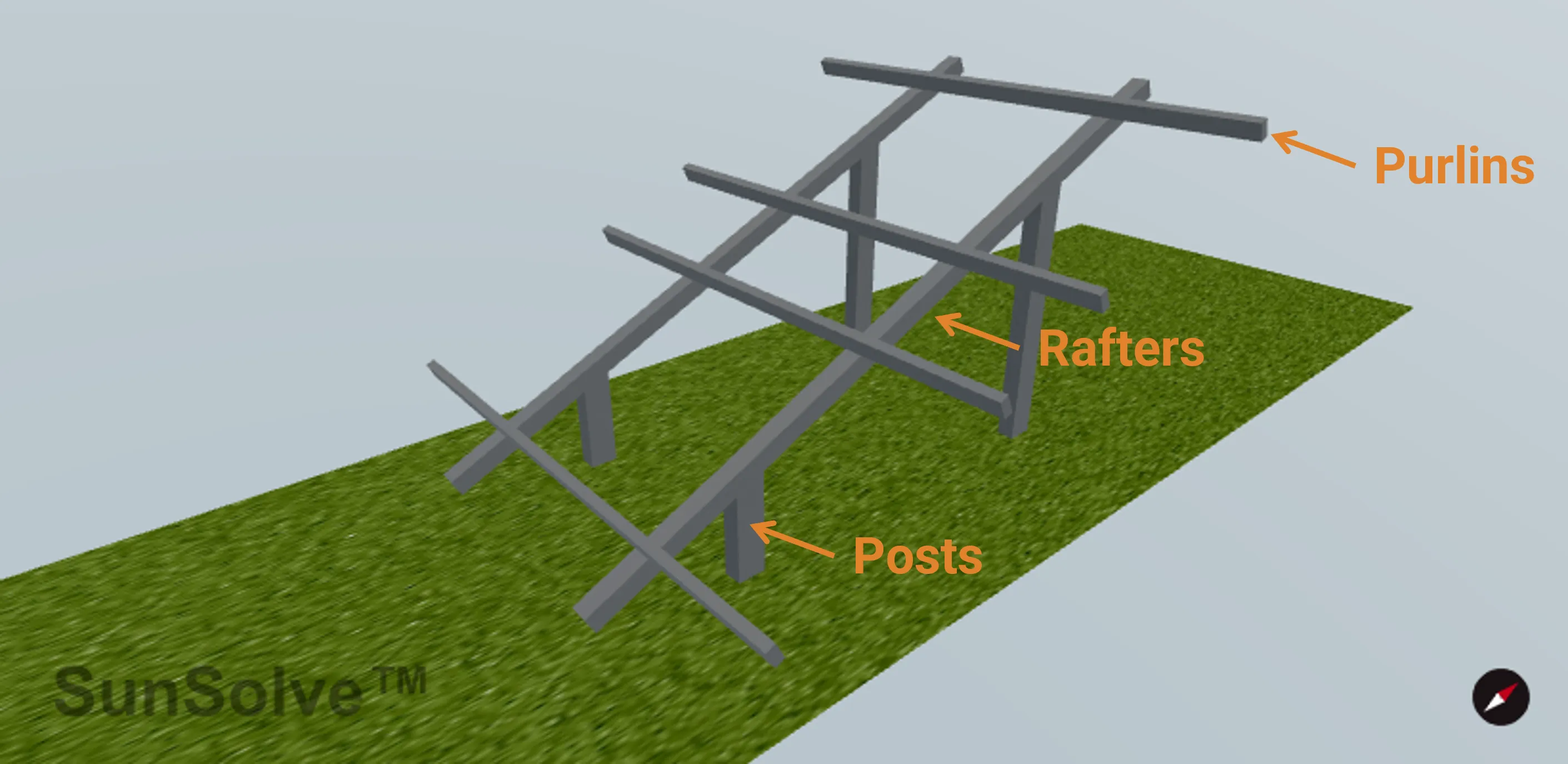
Section link: Fixed systemsA Fixed system can include purlins, rafters and posts. Modules sit on the purlins, or directly on the rafters when purlins are disabled. Purlins sit on the rafters, and posts attach beneath the rafters.
Purlins
Section link: PurlinsPurlins provide immediate support beneath the modules.
Cross section selects one of two shapes:
- Rectangular, defined by Width and Depth .
- Circular, defined by Diameter .
Orientation sets the direction in which each purlin runs:
- Horizontal runs parallel to the row axis.
- Vertical runs parallel to the tilt direction.
Length setting controls the purlin length:
- Match module group dimension spans the module group in the selected orientation and updates with the layout.
- Custom uses Length .
Alignment controls the number and position of the purlins:
- Centre of modules centres the specified Number within each module. Pitch sets their centre-to-centre separation when more than one is used.
- Edges of modules places two purlins at the module edges.
- Between modules places purlins in the gaps, including the outer edges of the module group.
Dist below sets the vertical distance from the bottom of the module group to the top of the purlin.
Purlins placed at a unit-system boundary use the shared edge-handling behaviour.
Rafters
Section link: RaftersRafters span the module group, support the purlins and provide the attachment for posts.
Cross section selects one of two shapes:
- Rectangular, defined by Width and Depth .
- Circular, defined by Diameter .
Orientation sets the direction in which each rafter runs:
- Horizontal runs parallel to the row axis.
- Vertical runs perpendicular to the row axis.
Length setting controls the rafter length:
- Match module group dimension spans the module group in the selected orientation and updates with the layout.
- Custom uses Length .
Positioning
Section link: PositioningNumber sets the number of rafters in the unit system. Pitch sets their centre-to-centre spacing. The rafters are distributed symmetrically about the system centre.
Rafters placed at a unit-system boundary use the shared edge-handling behaviour.
Fixed posts
Section link: Fixed postsPosts are available when rafters are enabled. They extend from the ground to the rafters.
Cross section selects one of two shapes:
- Rectangular, defined by Width and Breadth .
- Circular, defined by Diameter .
Top shape selects the geometry at the top of the post:
- Flat has no cap.
- Arch uses a half-cylinder cap.
- Hemispherical uses a half-sphere cap.
Layout
Section link: LayoutPosts align with the rafters in one direction. Layout controls their position in the perpendicular direction:
- Central distributes Number posts using Pitch . Offset from centre shifts the group along the rafter.
- Edge places one post at each edge of the rafter.
Posts placed at a unit-system boundary use the shared edge-handling behaviour.
Height
Section link: HeightFixed posts extend from the ground to the rafters. SunSolve calculates the height of each post from its position along the tilt direction:
where is the calculated axis height, is the At 0° tilt module height, is the purlin Dist below, is the purlin depth or diameter, is the rafter depth or diameter, is the module tilt, and is the post position along the tilt direction relative to the system centre. When purlins are disabled, and are zero.
Posts at different positions can therefore have different heights so that each reaches the tilted rafter. Fixed posts do not use the tracker Dist below module input.
Fixed axis of rotation
Section link: Fixed axis of rotationFor a Fixed system, the axis of rotation is the reference line about which SunSolve tilts the module group and its supporting structure to the configured angle. It is a geometry pivot rather than an axis that moves during operation.
The At 0° tilt module height on the Layout page sets the height of the bottom of the horizontal module group. SunSolve calculates the axis height from this reference and the enabled structure beneath it:
- With rafters and purlins, the axis passes through the vertical centre of the rafters. Its height is .
- With rafters but no purlins, the axis passes through the vertical centre of the rafters. Its height is .
- Without rafters, the axis is at the At 0° tilt module height . Purlins alone do not move the axis.
Changing the purlin depth, Dist below, or rafter depth changes the calculated axis height while preserving the entered At 0° tilt module height. Rafter length, number, pitch and orientation do not affect the axis height, and posts do not define it.
The result is shown as Height above ground under Axis of rotation on the Layout page. Fixed systems do not have the tracker Vertical offset input.
Single-axis tracker systems
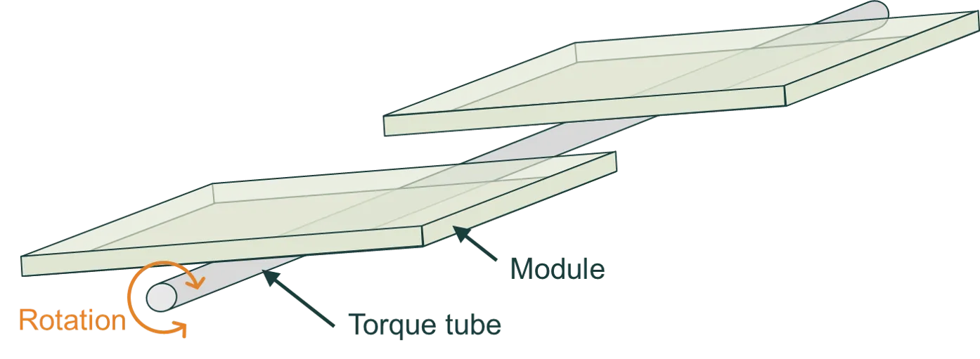
Section link: Single-axis tracker systemsA Single-axis tracker can include clamps, a torque tube and posts. The modules, clamps and torque tube rotate together, while the posts remain stationary.
Clamps
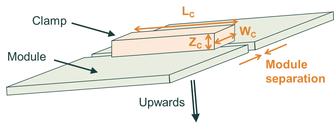
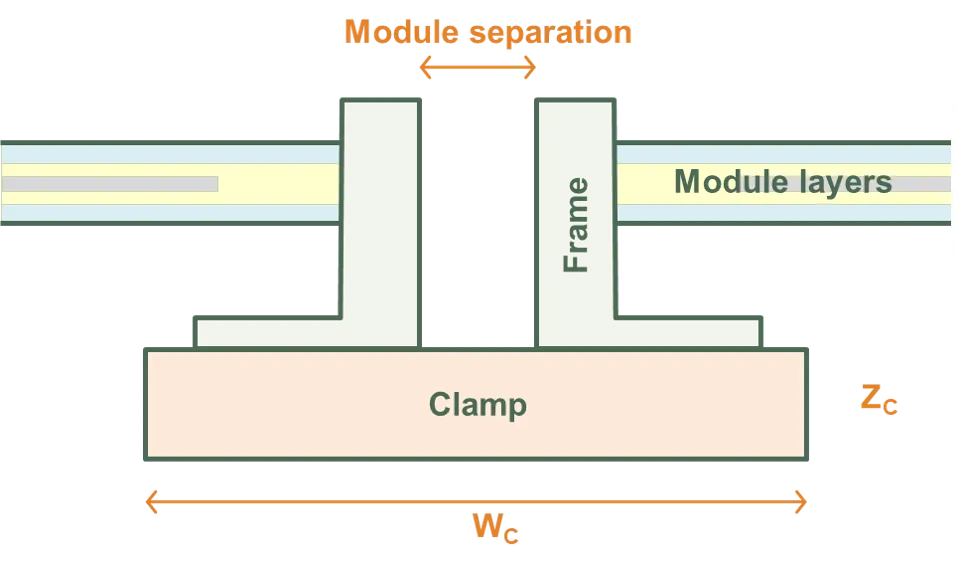
Section link: ClampsSunSolve represents clamps as rectangular prisms. Two clamps are created for each module.
Positioning
Section link: PositioningThe clamps sit immediately below the module frame, or below the module layers when no frame is present. In the XY plane, each clamp centre coincides with the centre of a module-separation gap. A clamp does not extend beyond the module spacing into the space surrounding the row.
Dimensions
Section link: Dimensions- Length runs along the module side.
- Width runs perpendicular to the module side.
- Height sets the clamp thickness.
Clamp geometry must fit within the module group and its separation. Clamp height must also fit between the module and the structures beneath it.
Torque tube
Section link: Torque tubeThe torque tube supports the rotating components and defines their default physical axis of rotation.
Cross section
Section link: Cross sectionCross section selects one of four shapes:
- Circular, defined by Diameter .
- Rectangular, defined by Width and Height .
- Hexagonal, defined by Inner diameter .
- Octagonal, defined by Inner diameter .
Positioning
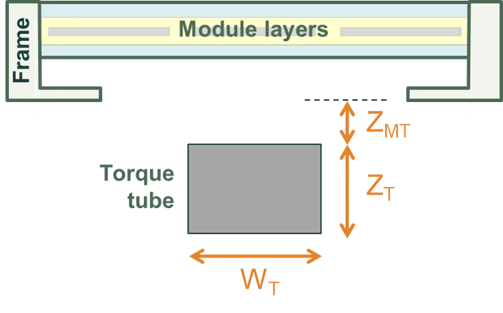
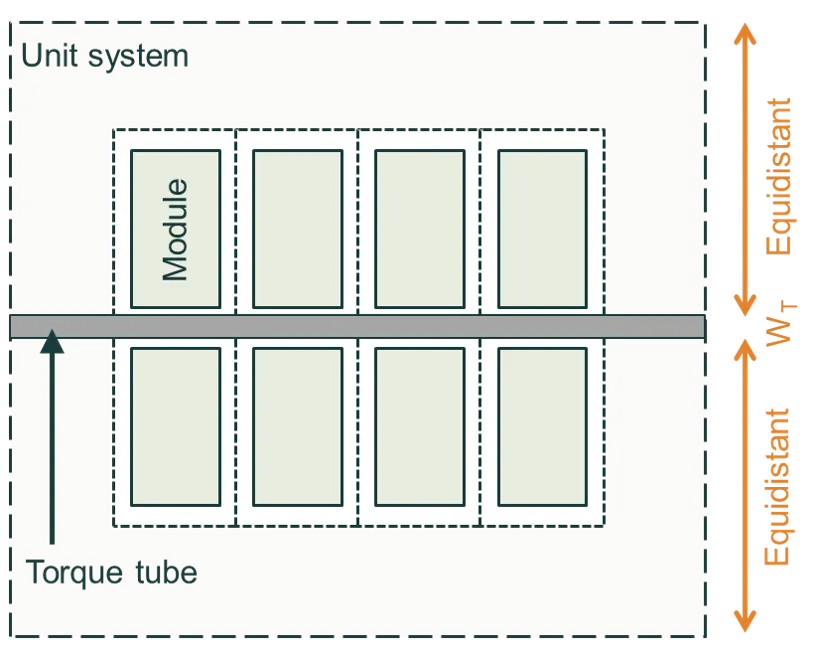
Section link: PositioningThe torque tube is centred in the unit system and extends to its boundary.
Dist below module group sets the vertical distance from the bottom of the module group to the top of the torque tube.
Tracker posts
Section link: Tracker postsPosts remain stationary while the modules, clamps and torque tube rotate.
Cross section selects one of two shapes:
- Rectangular, defined by X dimension and Y dimension .
- Circular, defined by Diameter .
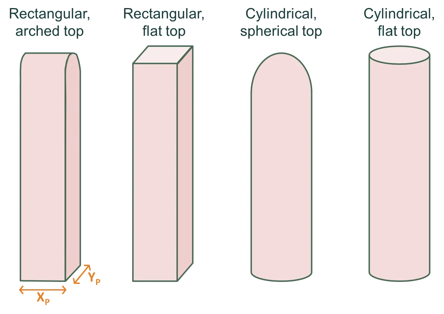
Top shape selects the geometry at the top of the post:
- Flat is available for rectangular and circular posts.
- Arch uses a half-cylinder cap and is available for rectangular posts.
- Hemispherical uses a half-sphere cap and is available for circular posts.
Layout controls the position of posts along the tracker axis:
- Central distributes Number of posts using Post-to-post pitch .
- Edge places posts at the unit-system boundaries.
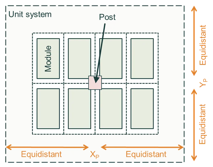
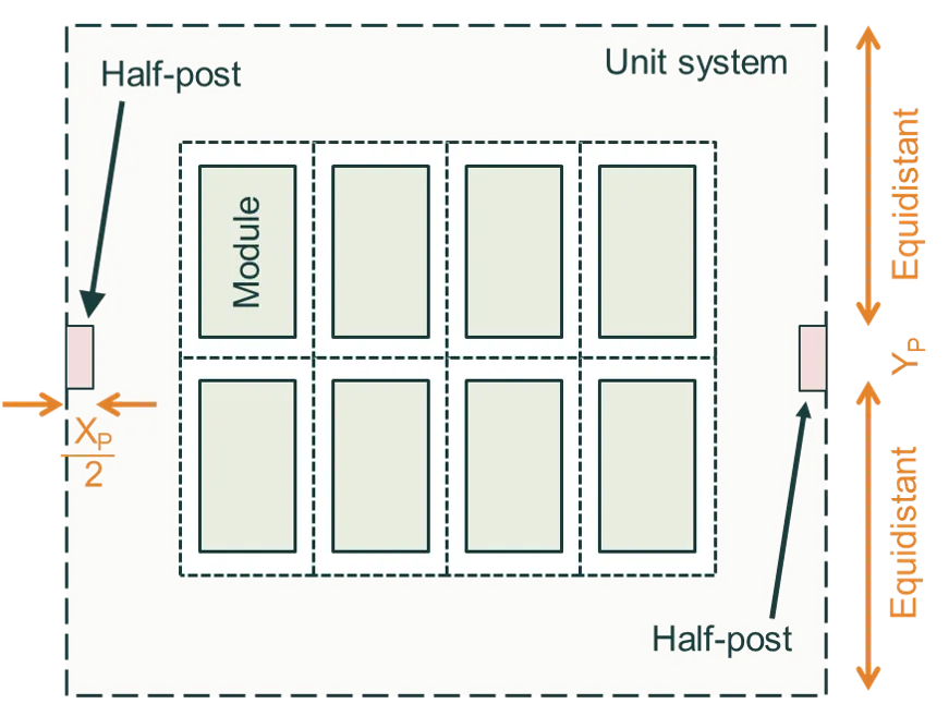
When a post reaches a unit-system boundary, it is rendered flush with that boundary so the structure tiles correctly. See Edge handling.
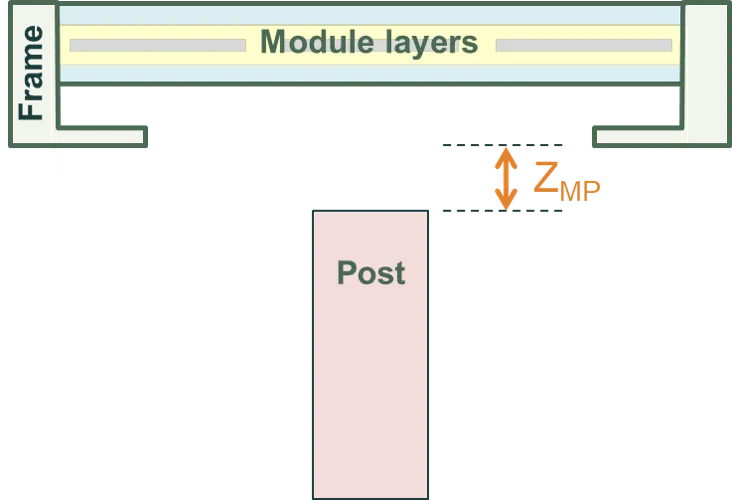
Dist from top of post to bottom of panel defines the vertical gap used to calculate the post height.
Tracker axis of rotation
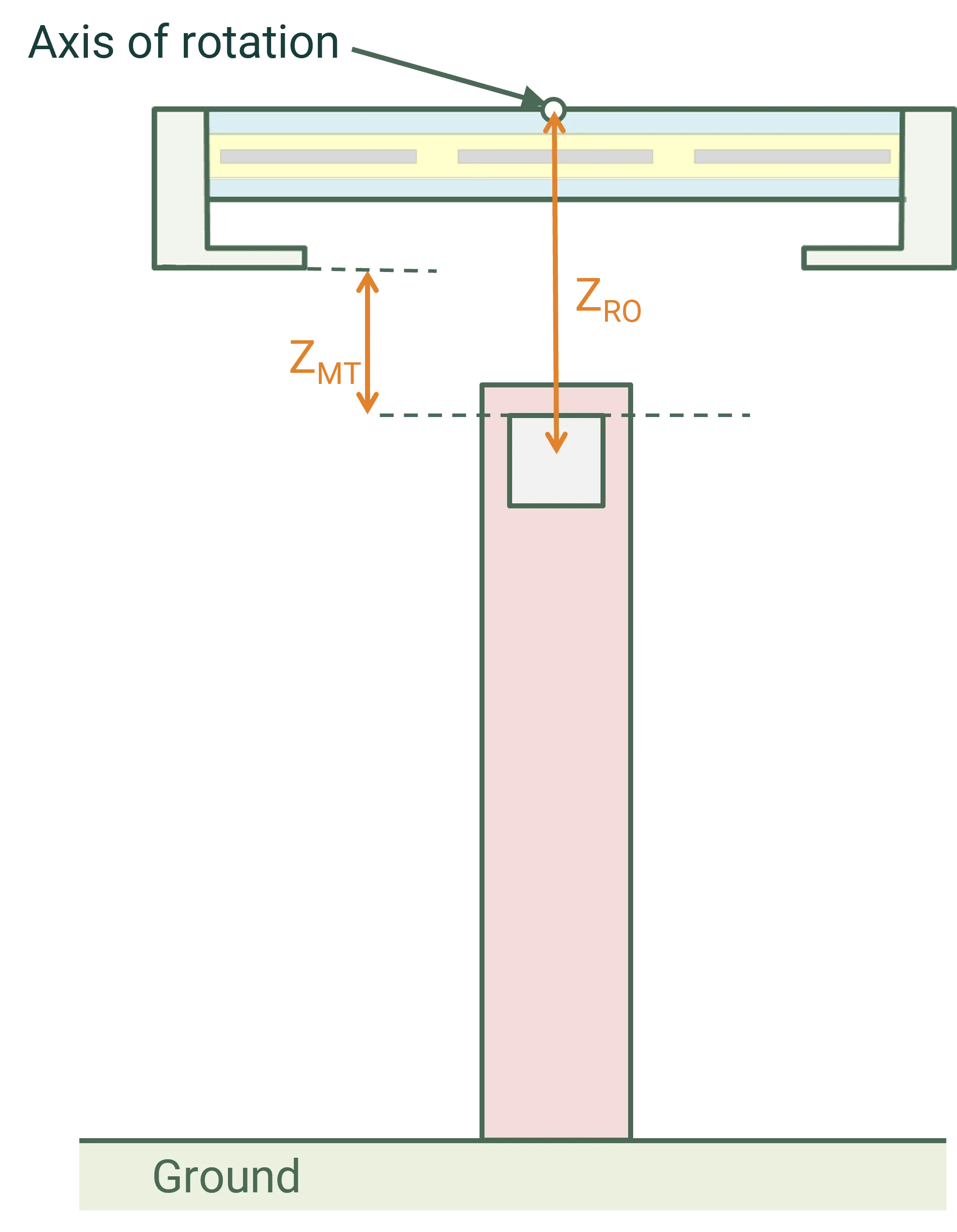
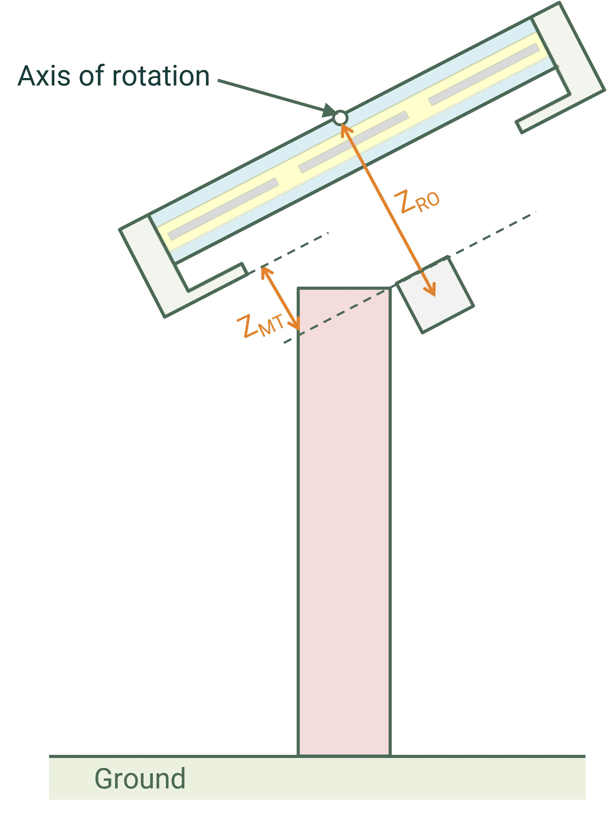
Section link: Tracker axis of rotationThe default physical axis depends on whether the torque tube is enabled:
- With a torque tube, the module group, clamps and tube rotate about the tube axis.
- Without a torque tube, the module group and clamps rotate about an axis through the module-group centre in the XY plane and the bottom of the module group in the Z direction.
Posts do not rotate in either case.
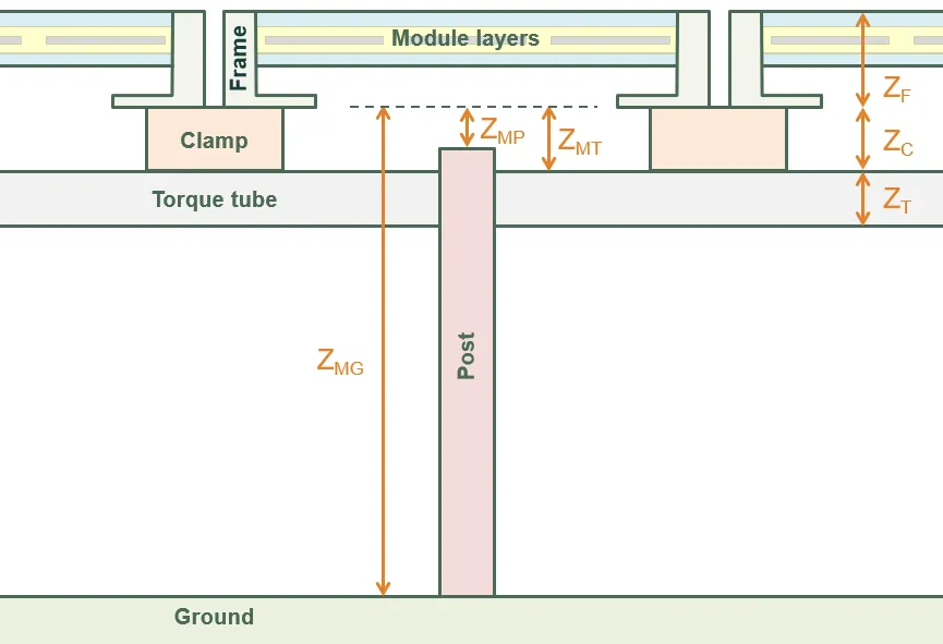
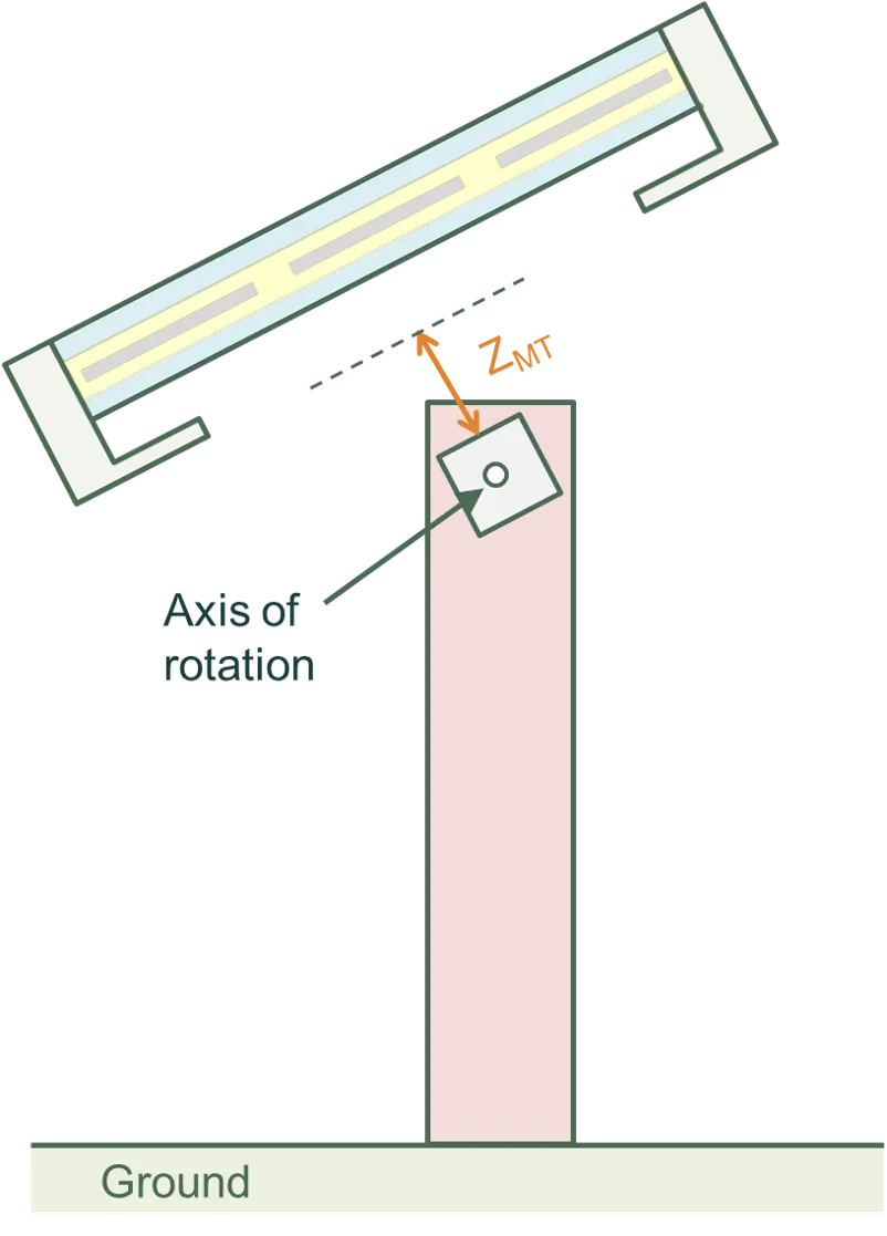
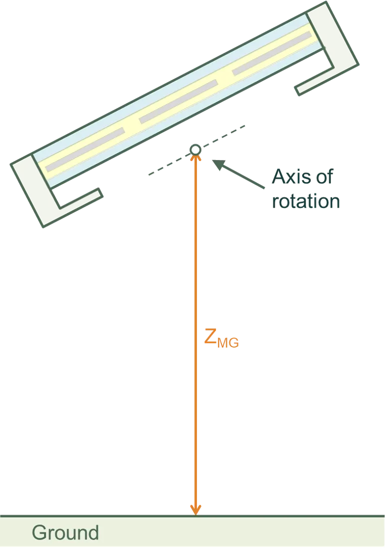
The Vertical offset Layout input shifts the rotation point from this default position. The offset applies to the module group and rotating components, but not to the posts.
Waves systems
Section link: Waves systemsA Waves system can include ballast support beams, standoffs, stabiliser wires, rails and joints. These components also determine the module height.
Ballast block
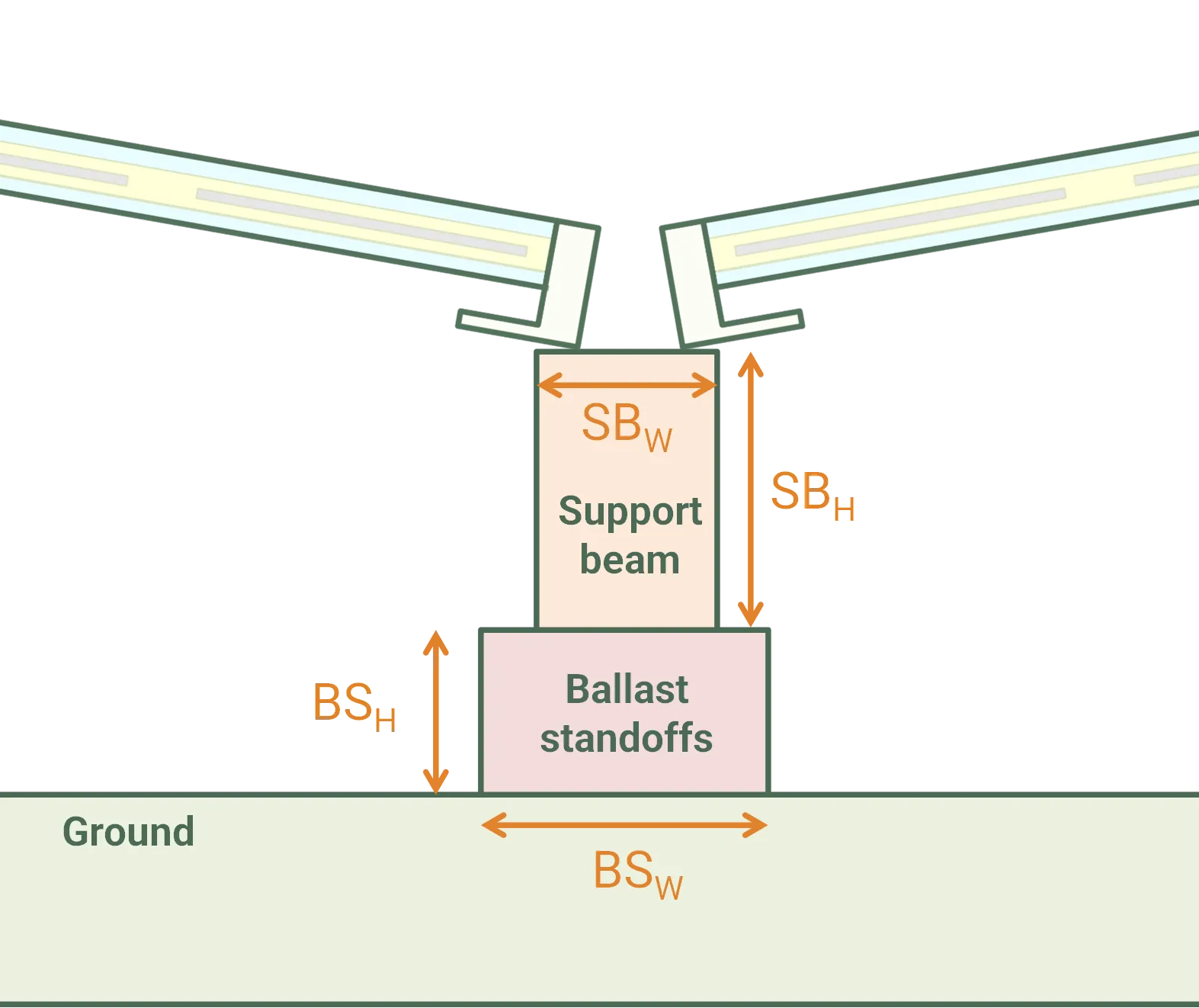
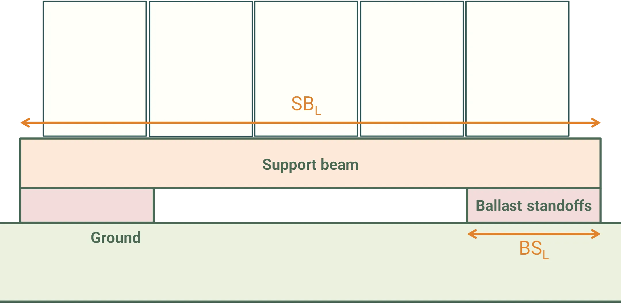
Section link: Ballast blockThe ballast block consists of a support beam with optional standoffs and stabiliser wires. The support beam sits on the ground. SunSolve represents the support beam and standoffs as rectangular prisms and each stabiliser wire as a cylinder.
Support beam
Section link: Support beamThe support beam is defined by Width , Height and Length .
Standoffs
Section link: StandoffsStandoffs are available only when the ballast block is enabled. Each standoff is defined by Width , Height and Length .
Number of standoffs sets the count on each support beam. The spacing option positions them symmetrically about the support-beam centre:
- Evenly spaced aligns the outer edges of the first and last standoffs with the support-beam edges and distributes the remaining standoffs uniformly.
- Fixed pitch uses Pitch and allows the outer standoffs to sit back from the support-beam edges.
Stabiliser wires
Section link: Stabiliser wiresEach stabiliser wire is defined by Diameter and Offset from edge .
Rails
Section link: RailsRails support the modules at their corners. The lower rails sit at the wave trough and the upper rails at the wave peak. Their vertical reference is the top of the ballast support beam, or the ground when no support beam is present.
Arrangement
Section link: ArrangementArrangement controls the lateral rail positions:
- Aligned to module edges centres rails in the gaps between modules. The module sits on top of the bracket. At each wave edge, a rail has one inward-facing bracket.
- Grouped per module distributes Number of rails around each module using Rail pitch . The group is centred on the module, the rail is inverted relative to the edge-aligned arrangement, and the module sits at the lowest point of the bracket. This arrangement requires advanced Waves permissions.


Dimensions
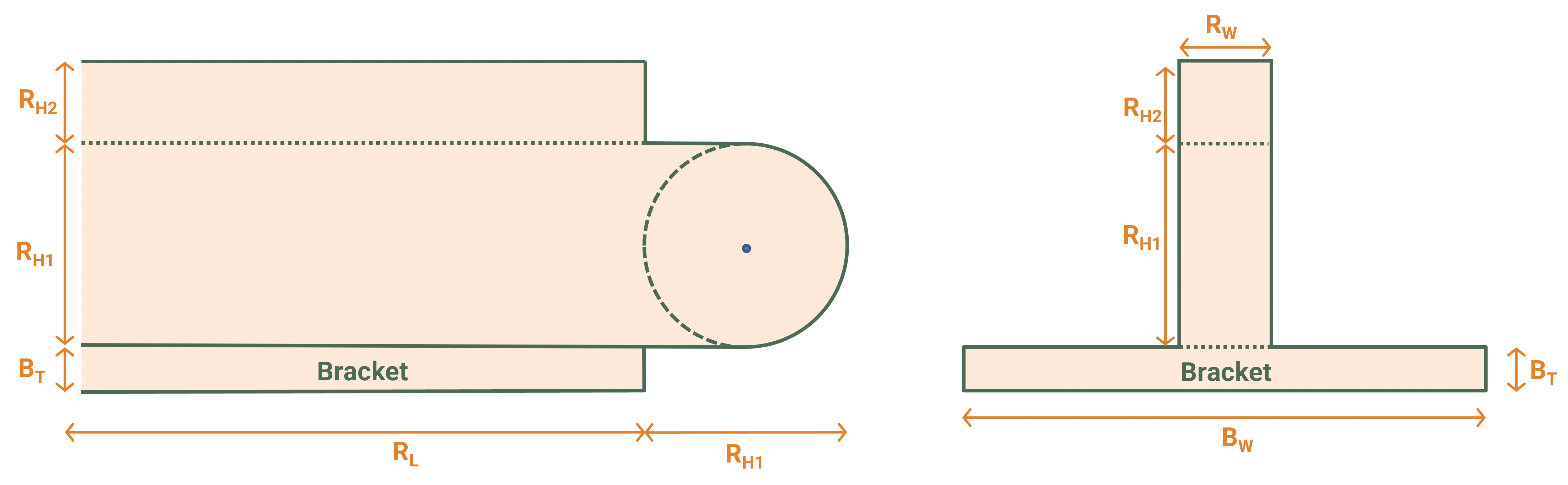
Section link: DimensionsThe rail shape consists of a bracket and two rail sections:
- Rail length runs along the module edge.
- Rail inner width defines the channel width.
- Rail height (main) includes the circular joint whose centre defines the rotation point.
- Rail extra height extends the rail above the main section.
- Bracket width and Bracket height define the module support.
- Rotation height sets the vertical distance from the support-beam or ground reference to the rotation point.
Joints
Section link: JointsJoints are available only when rails are enabled. They form rectangular blocks across the rail rotation points and are placed laterally wherever rails occur.
The upper joints are at the wave peaks and align vertically with the top of the unit-system box. The lower joints are at the wave troughs and sit on the support beam, or on the ground when no support beam is present. Joints do not change the module height or axis of rotation.
The lower and upper joints have separate Width, Height and Breadth inputs. Width is perpendicular to the wave direction and breadth is along the wave direction.
Waves system height
Section link: Waves system heightThe ballast and rail geometry determines the module height; Waves therefore has no independent Module height above ground input on the Layout sub-tab.
The common height terms are the ballast standoff height , support-beam height and rail rotation height . The rail arrangement then determines the remaining terms.
Aligned to module edges
Section link: Aligned to module edges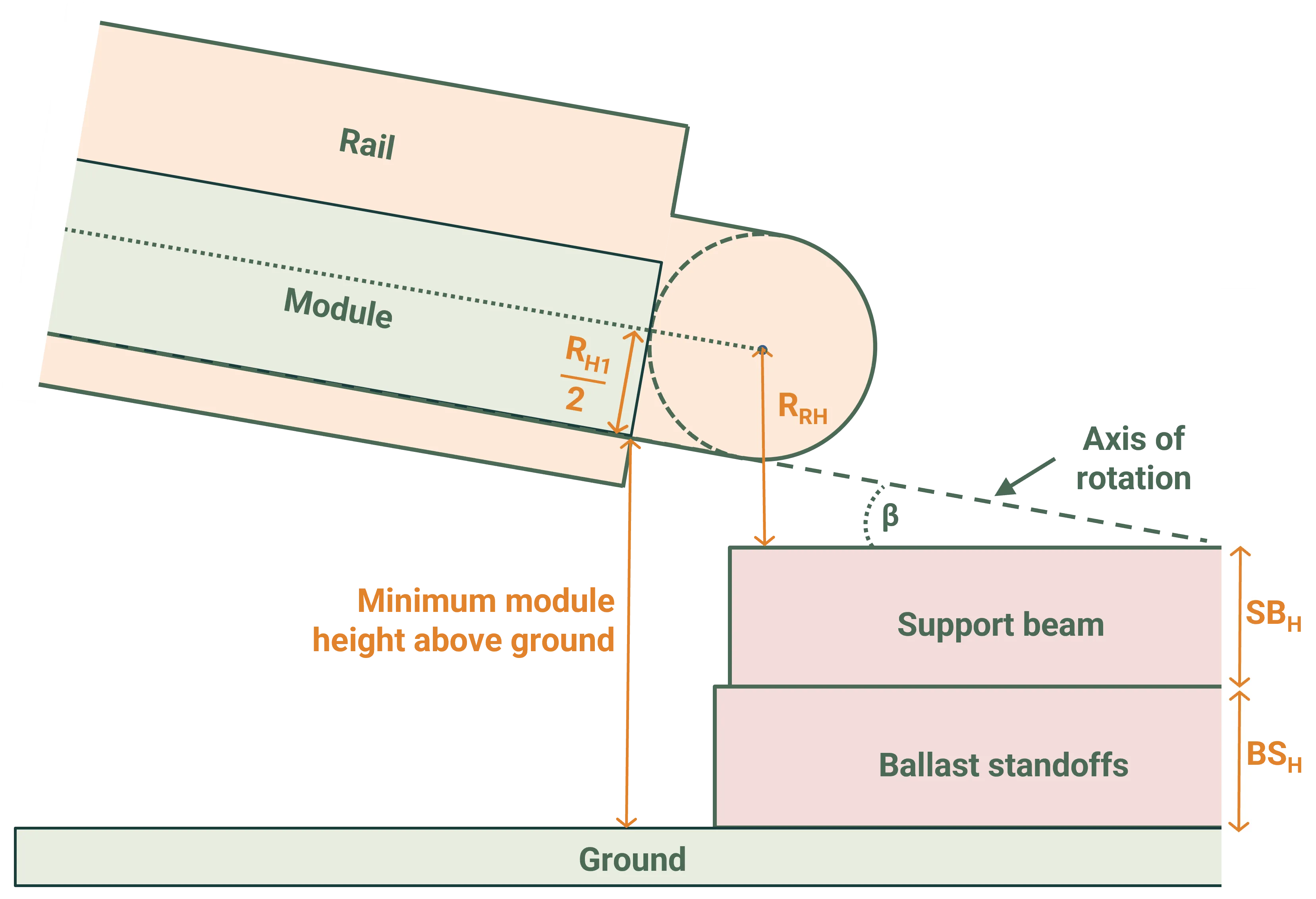
For Aligned to module edges, the module height is
where is the module length in the tilt direction.
Grouped per module
Section link: Grouped per module
For Grouped per module, the module height is
In both equations, the final term is the vertical contribution from the tilted module.
Waves axis of rotation
Section link: Waves axis of rotationThe axis of rotation is aligned with the bottom edge of each module and passes through the circular joint in the main rail section. The ballast support beam, standoffs and Rotation height determine its height above ground. Unlike Fixed and Single-axis tracker systems, Waves has no separate Axis of rotation group on the Layout sub-tab.
Edge handling
Section link: Edge handlingWhen a structural element is positioned such that its width (the cross-sectional dimension perpendicular to its length) would extend beyond the unit-system boundary, it is automatically rendered as a half-width element flush with the boundary. This ensures the structure tiles correctly when the unit system repeats infinitely, without gaps or overlaps. It applies to purlins, rafters, and posts in fixed systems, and to posts in tracker systems.
How it works:
- The element’s orientation determines which unit-system boundary is checked (X or Y axis).
- The system detects when an element’s position along that axis would cause its width to extend past the boundary.
- For circular cross-sections, a half-cylinder is created (semi-circular profile).
- For rectangular cross-sections, the width (perpendicular to length) is halved.
- The element is positioned so its flat edge aligns with the unit-system boundary.
- The length is unchanged: the “Match module group dimension” setting sizes the length to fit within the boundary, and custom lengths are assumed to fit.
The behaviour applies to elements whose position places them at a boundary:
- Purlins in “Between modules” alignment mode, where the first and last purlins may sit at edges.
- Rafters where the number and pitch result in rafters at unit-system edges.
- Posts where the layout and spacing result in posts at unit-system edges.
Custom length values are not calculated against the system boundaries. Use “Match module group dimension” to ensure elements fit correctly.