
System inputs
The System tab defines the arrangement, mounting structure and surroundings of the PV modules. It builds the 3D scene that will be ray traced.
At the top of the tab is the system image, which provides a preview of the scene. Beneath the 3D drawing is a set of sub-tabs used to define the system.
System tab sections
Section link: System tab sectionsLayout, Select the system type and define the module arrangement,, orientation,, dimensions and height.
Structure, Configure the standard mounting structure for the selected system type. Additional geometry can be added as custom objects.
The system image above the sub-tabs updates with the inputs and shows the resulting layout, structure and dimensions.
Unit system
Section link: Unit systemEach system type is defined as a unit system, which is a representative section that repeats infinitely in both horizontal directions.
For the theory behind the repeated unit system and the scaling of ray-traced results, see Ray tracing methodology and Main solving algorithm. The permitted number of modules depends on the module type and fidelity level; see Unit-system size limits.
Simulating a central module
Section link: Simulating a central moduleA unit system containing one module can represent a module far from the edges of a large array. Set the module separation to zero and define the unit-system dimensions to reproduce the pitch and spacing of the surrounding modules.
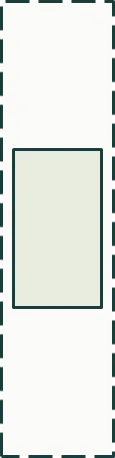
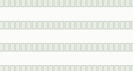
Figure: A single-module unit system and the equivalent infinitely repeated array.